This thread has been locked.

If you have a related question, please click the "Ask a related question" button in the top right corner. The newly created question will be automatically linked to this question.

DS90UB954-Q1EVM: CSI2 CLOCK signal error

Part Number: DS90UB954-Q1EVM

Tool/software:

Hello TI Team,

We are interfacing the DS90UB954-Q1EVM board with the Jetson Orin Nano Developer Kit Carrier Board using an adapter board.
However, when using the CSI interface to transmit data to the Orin board, we are not receiving any data.
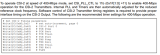
We checked the differential clock signal for the CSI, and at 1600 Mbps, the signal resembles the image shown below. When we reduced the speed to 400 Mbps, the signal improved, but it is still not clean.
One point : REFCLK_FREQ register shows a 24Mhz or the assembled REFCLK is 25Mhz.
I also uploaded the register configs.

Could you please provide guidance about this issue?

Best regards,

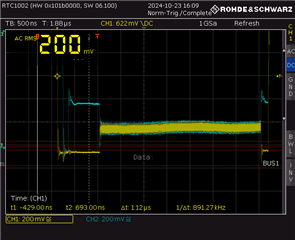
0x0: 0x60
0x1: 0x00
0x2: 0x1e
0x3: 0x20
0x4: 0xd3
0x5: 0x01
0x6: 0x00
0x7: 0xfe
0x8: 0x1c
0x9: 0x10
0xA: 0x7a
0xB: 0x7a
0xC: 0x83
0xD: 0x09
0xE: 0x08
0xF: 0x7f
0x10: 0x00
0x11: 0x00
0x12: 0x00
0x13: 0x00
0x14: 0x00
0x15: 0x00
0x16: 0x00
0x17: 0x00
0x18: 0x00
0x19: 0x00
0x1A: 0x00
0x1B: 0x00
0x1C: 0x00
0x1D: 0x00
0x1E: 0x04
0x1F: 0x03
0x20: 0x30
0x21: 0x01
0x22: 0x00
0x23: 0x00
0x24: 0x00
0x25: 0x00
0x26: 0x00
0x27: 0x00
0x28: 0x00
0x29: 0x00
0x2A: 0x00
0x2B: 0x00
0x2C: 0x00
0x2D: 0x00
0x2E: 0x00
0x2F: 0x00
0x30: 0x00
0x31: 0x00
0x32: 0x00
0x33: 0x01
0x34: 0x40
0x35: 0x00
0x36: 0x00
0x37: 0x00
0x38: 0x00
0x39: 0x00
0x3A: 0x00
0x3B: 0x01
0x3C: 0x14
0x3D: 0x6f
0x3E: 0x00
0x3F: 0x40
0x40: 0x00
0x41: 0xe0
0x42: 0x71
0x43: 0x01
0x44: 0x00
0x45: 0x00
0x46: 0x00
0x47: 0x00
0x48: 0x00
0x49: 0x00
0x4A: 0x00
0x4B: 0x12
0x4C: 0x01
0x4D: 0x00
0x4E: 0x02
0x4F: 0x00
0x50: 0x00
0x51: 0x00
0x52: 0x00
0x53: 0x00
0x54: 0x00
0x55: 0x00
0x56: 0x00
0x57: 0x00
0x58: 0x1e
0x59: 0x00
0x5A: 0x00
0x5B: 0x00
0x5C: 0x00
0x5D: 0x00
0x5E: 0x00
0x5F: 0x00
0x60: 0x00
0x61: 0x00
0x62: 0x00
0x63: 0x00
0x64: 0x00
0x65: 0x00
0x66: 0x00
0x67: 0x00
0x68: 0x00
0x69: 0x00
0x6A: 0x00
0x6B: 0x00
0x6C: 0x00
0x6D: 0x7c
0x6E: 0x88
0x6F: 0x88
0x70: 0x2b
0x71: 0x2c
0x72: 0xe4
0x73: 0x00
0x74: 0x00
0x75: 0x00
0x76: 0x00
0x77: 0xc5
0x78: 0x00
0x79: 0x01
0x7A: 0x00
0x7B: 0x00
0x7C: 0x20
0x7D: 0x00
0x7E: 0x00
0x7F: 0x00
0x80: 0x00
0x81: 0x00
0x82: 0x00
0x83: 0x00
0x84: 0x00
0x85: 0x00
0x86: 0x00
0x87: 0x00
0x88: 0x00
0x89: 0x00
0x8A: 0x00
0x8B: 0x00
0x8C: 0x00
0x8D: 0x00
0x8E: 0x00
0x8F: 0x00
0x90: 0x00
0x91: 0x00
0x92: 0x00
0x93: 0x00
0x94: 0x00
0x95: 0x00
0x96: 0x00
0x97: 0x00
0x98: 0x00
0x99: 0x00
0x9A: 0x00
0x9B: 0x00
0x9C: 0x00
0x9D: 0x00
0x9E: 0x00
0x9F: 0x00
0xA0: 0x02
0xA1: 0x0f
0xA2: 0x00
0xA3: 0x00
0xA4: 0x08
0xA5: 0x18
0xA6: 0x00
0xA7: 0x00
0xA8: 0x00
0xA9: 0x00
0xAA: 0x00
0xAB: 0x00
0xAC: 0x00
0xAD: 0x00
0xAE: 0x00
0xAF: 0x00
0xB0: 0x00
0xB1: 0x0f
0xB2: 0x0a
0xB3: 0x08
0xB4: 0x25
0xB5: 0x00
0xB6: 0x18
0xB7: 0x00
0xB8: 0x8c
0xB9: 0x33
0xBA: 0x83
0xBB: 0x74
0xBC: 0x80
0xBD: 0x00
0xBE: 0x00
0xBF: 0x00
0xC0: 0x00
0xC1: 0x00
0xC2: 0x00
0xC3: 0x00
0xC4: 0x00
0xC5: 0x00
0xC6: 0x00
0xC7: 0x00
0xC8: 0x00
0xC9: 0x00
0xCA: 0x00
0xCB: 0x00
0xCC: 0x00
0xCD: 0x00
0xCE: 0x00
0xCF: 0x00
0xD0: 0x00
0xD1: 0x43
0xD2: 0x94
0xD3: 0x03
0xD4: 0x60
0xD5: 0xf2
0xD6: 0x00
0xD7: 0x01
0xD8: 0x00
0xD9: 0x00
0xDA: 0x00
0xDB: 0x00
0xDC: 0x00
0xDD: 0x00
0xDE: 0x00
0xDF: 0x00
0xE0: 0x00
0xE1: 0x00
0xE2: 0x00
0xE3: 0x00
0xE4: 0x00
0xE5: 0x00
0xE6: 0x00
0xE7: 0x00
0xE8: 0x00
0xE9: 0x00
0xEA: 0x00
0xEB: 0x00
0xEC: 0x00
0xED: 0x00
0xEE: 0x00
0xEF: 0x00
0xF0: 0x5f
0xF1: 0x55
0xF2: 0x42
0xF3: 0x39
0xF4: 0x35
0xF5: 0x34
0xF6: 0x00
0xF7: 0x00
0xF8: 0x00
0xF9: 0x00
0xFA: 0x00
0xFB: 0x00
0xFC: 0x00
0xFD: 0x00
0xFE: 0x00
0xFF: 0x00

  • Hi Mohamed, 

    For the 400 Mbps settings of the CSI transmitter, please confirm the following is being implemented as well: 

    Additionally, are you using DES pat gen or trying to forward data from an input serializer? In order to forward data from RX ports, this must be configured in register 0x20. Currently, forwarding from RX port 0 and RX port 1 is disabled in 0x20. 

    Best,

    Zoe

  • Hello Zoe,
    Yes, the shared setting has been implemented, but nothing has changed in the signal.
    First we tried to forward data from an input serializer, then we used DES pat gen and the same problem appears “No CSI Diff clock”

  • Hi Mohamed, 

    In the register dump that was provided are you trying to use des PATGEN? Would you be able to provide the script for configuring DES patgen? 

    Best,

    Zoe

  • Hi Zoe,

    yes, we are using the des patgen, please find below the script:


    #!/bin/bash

    # Define bus and device addresses
    bus=9
    deserAddr=0x30

    i2cset -f -y $bus $dev 0x33 0x01   # CSI0 enable

    # Indirect Pattern Gen Registers
    i2cset -f -y $bus $deserAddr 0xB0 0x00   # Indirect register
    i2cset -f -y $bus $deserAddr 0xB1 0x01   # PGEN_CTL
    i2cset -f -y $bus $deserAddr 0xB2 0x01

    i2cset -f -y $bus $deserAddr 0xB1 0x02   # PGEN_CFG
    i2cset -f -y $bus $deserAddr 0xB2 0x33

    i2cset -f -y $bus $deserAddr 0xB1 0x03   # PGEN_CSI_DI
    i2cset -f -y $bus $deserAddr 0xB2 0x24

    # Pattern Generator for 1280x720p30
    i2cset -f -y $bus $deserAddr 0xB1 0x04   # PGEN_LINE_SIZE1 (1280 = 0x0500, high byte is 0x05)
    i2cset -f -y $bus $deserAddr 0xB2 0x05   # High byte
    i2cset -f -y $bus $deserAddr 0xB1 0x05   # PGEN_LINE_SIZE0 (1280 = 0x0500, low byte is 0x00)
    i2cset -f -y $bus $deserAddr 0xB2 0x00   # Low byte

    i2cset -f -y $bus $deserAddr 0xB1 0x06   # PGEN_BAR_SIZE1
    i2cset -f -y $bus $deserAddr 0xB2 0x01
    i2cset -f -y $bus $deserAddr 0xB1 0x07   # PGEN_BAR_SIZE0
    i2cset -f -y $bus $deserAddr 0xB2 0xE0

    i2cset -f -y $bus $deserAddr 0xB1 0x08   # PGEN_ACT_LPF1 (720 = 0x02D0, high byte is 0x02)
    i2cset -f -y $bus $deserAddr 0xB2 0x02   # High byte
    i2cset -f -y $bus $deserAddr 0xB1 0x09   # PGEN_ACT_LPF0 (720 = 0x02D0, low byte is 0xD0)
    i2cset -f -y $bus $deserAddr 0xB2 0xD0   # Low byte

    i2cset -f -y $bus $deserAddr 0xB1 0x0A   # PGEN_TOT_LPF1 (1080 = 0x041A, high byte is 0x04)
    i2cset -f -y $bus $deserAddr 0xB2 0x04   # High byte
    i2cset -f -y $bus $deserAddr 0xB1 0x0B   # PGEN_TOT_LPF0 (1080 = 0x041A, low byte is 0x1A)
    i2cset -f -y $bus $deserAddr 0xB2 0x1A   # Low byte

    i2cset -f -y $bus $deserAddr 0xB1 0x0C   # PGEN_LINE_PD1
    i2cset -f -y $bus $deserAddr 0xB2 0x0C
    i2cset -f -y $bus $deserAddr 0xB1 0x0D   # PGEN_LINE_PD0
    i2cset -f -y $bus $deserAddr 0xB2 0x67

    i2cset -f -y $bus $deserAddr 0xB1 0x0E   # PGEN_VBP
    i2cset -f -y $bus $deserAddr 0xB2 0x21

    i2cset -f -y $bus $deserAddr 0xB1 0x0F   # PGEN_VFP
    i2cset -f -y $bus $deserAddr 0xB2 0x0A

  • Hi Mohammed, 

    Would you be able to share the layout for the adapter board that is being used? I recommend taking a look to see if all connections to the adapter are connected properly and nothing is loose in the meantime. 

    Best,

    Zoe

  • Hi Zoe,

    Here are the gerber file of the adapter board.

    Gerberdaten.zip

  • Hi Mohammed, 

    I took another look at this script and noticed some errors in the register assignments here. Please reference the following below: 

    Register Data Name
    0x0001 0x01 PGEN_CTL
    0x0002 0x33 PGEN_CFG
    0x0003 0x24 PGEN_CSI_DI
    0x0004 0x0F PGEN_LINE_SIZE1
    0x0005 0x00 PGEN_LINE_SIZE0
    0x0006 0x01 PGEN_BAR_SIZE1
    0x0007 0xE0 PGEN_BAR_SIZE0
    0x0008 0x02 PGEN_ACT_LPF1
    0x0009 0xD0 PGEN_ACT_LPF0
    0x000A 0x02 PGEN_TOT_LPF1
    0x000B 0xFD PGEN_TOT_LPF0
    0x000C 0x11 PGEN_LINE_PD1
    0x000D 0x05 PGEN_LINE_PD0
    0x000E 0x21 PGEN_VBP
    0x000F 0x0A PGEN_VFP

    How is the CSI signal being measured here and what is the bandwidth of the scope being used? 

    Best,

    Zoe

  • Hi Zoe,

    We tried the proposed script, but there were no changes.
    We ordered another evaluation board, as we suspect the deserializer board might be defective. We’ll keep you updated once we test the new board.

  • Hi Mohamed, 

    Thanks, let me know if there are any updates. 

    Best,

    Zoe

  • Hi Zoe,

    Thank you for your support.
    The problem was solved, it was a miss configuration from orin board side.

    Br,