This thread has been locked.

If you have a related question, please click the "Ask a related question" button in the top right corner. The newly created question will be automatically linked to this question.

TUSB522P: Trace length

Part Number: TUSB522P
Other Parts Discussed in Thread: TUSB1002A

Tool/software:

Hi Expert,

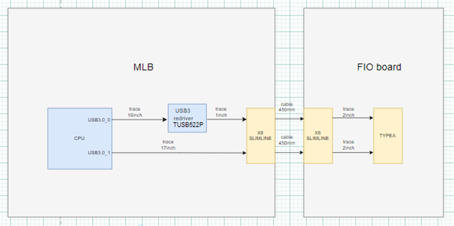
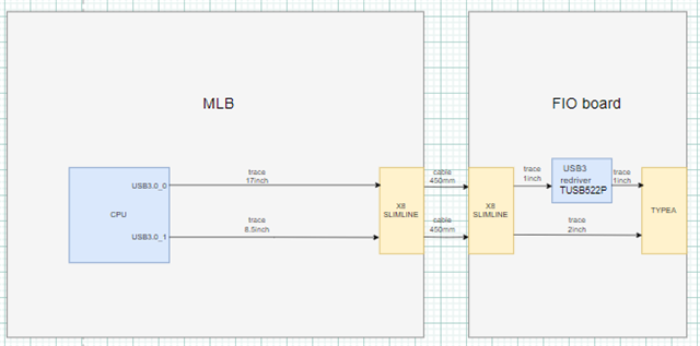
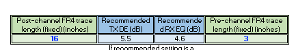
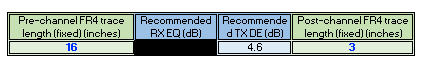
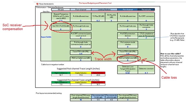
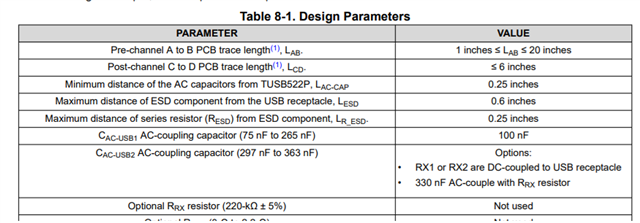
Do the following design parameters mean that the trace length range from HOST to REDRIVER supported by TUSB522P on FR4 PCB board is 1-20 inches, and does the trace length from REDRIVER to terminal connector be less than 6 inches? If the above understanding is not correct, is the trace length spec Can it be used as a reference for customers?

Regards,
Hailiang

  • Hi Hailiang,

    Those design parameters have worked for us in our internal testing, but high speed performance is very system-dependent. 5 Gbps signals are sensitive to trace material, number of vias, trace routing, connectors,... so it is hard to give a solid number that will work in all scenarios.

    These parameters should be taken as a guideline, not as a guarantee. For example, if your customer uses a high quality/low-loss material for the signal trace, its possible the length could be extended further than what is shown. On the other hand, if the trace material is lossy, you may not reach 20" and 6" of trace length.

    If your customer has a system idea in mind I can help gauge whether it would be realistic with our TUSB522P. Let me know if you have any other questions as well.

    Best,

    Shane

  • Hi Shane,

    Customers are considering two topologies. That is, there are two ways to put the redriver, on the motherboard or on the FIO board. The block diagram is as follows. You can see that the two boards are connected by 2 Slimline connectors and a 450mm long cable. The customer SI engineer assessed the loss in this part to be 3dB@2.5GHz. In addition, the customer considers PCB made of FR4 material, and the loss of 1-inch trace is 0.4dB@2.5GHz. Please help evaluate whether TUSB522P is feasible? Which way is better?

    Topology 1:

    Topology 2:

    Regards,
    Hailiang

  • Hi Shane,

    May I expect your reply by end of this week? Thanks.

    Regards,
    Hailiang

  • Hi Hailiang,

    We use a budgeting tool to help decide whether the system proposal is realistic. I'll share the tool here (the password is 'ti'):

    RX & TX trace length budgeting.xlsx

    Since the TUSB522P is a limited re-driver, use the limiting re-driver TX and RX tabs for this calculation. The goal is to get a valid number in the blue boxes at the bottom-center of both the TX and RX 'limiting redriver' tabs:

    If you get a black box in one of these blue cells, it means we cannot compensate a portion of the channel. In this case, it's better to reduce the channel loss or move the TUSB522P to a better position

    I've put most of your system parameters into the tool already and what I'm seeing is that our re-driver would be better on the motherboard, but the 16" trace between the 522P and SoC is too long for our TUSB522P to compensate. To be certain, I'd like to know a few more things about your design:

    - What is the loss of the 450mm cable (in dB)?

    - How much receiver compensation does your SoC have (in dB)?

    - I put example values for the trace width and via count. If you know these parameters please help fill them into the tool

    Best,

    Shane

  • Hi Shane,

    Pls refer to the below reply.

    - What is the loss of the 450mm cable (in dB)?

    About 3dB@2.5GHz.

    - How much receiver compensation does your SoC have (in dB)?

    We don't have the exact data.

    It looks like the topology 1(re-driver on the motherboard)  doesn't meet customer needs, and the data for the second topology might be even worse, right? Are there any other suggestions and recommended alternative devices? 

    Regards,
    Hailiang

  • Hi Hailiang,

    It looks like the topology 1(re-driver on the motherboard)  doesn't meet customer needs, and the data for the second topology might be even worse, right?

    Correct. Topology 1 is better and our TUSB522P cannot compensate the entire 16" loss between the 522P and the USB host. While we cannot compensate the entire path, your system does still fall within the loss budget defined by the USB spec. Let me explain:

    The USB3 spec defines a loss budget for a USB host, device and cable that is acceptable to maintain good quality connections. For a host application, the loss budget is -10dB:

    In your design, I estimate about -12dB loss on the 16in trace between the 522P and the USB host. Since the 522P provides up to 9dB of EQ, we can add 9 to this loss to get a net loss of -3dB on the TX path. This falls within the USB loss budget of -10dB.

    Please note that these calculations are based on the trace parameters I have in the image below. If you make changes (adding more vias, reducing trace width,...) then my estimation would not be accurate.

    I am also assuming that your SoC has at least 6dB of EQ in my calculation. This is important to confirm, as the SoC needs to compensate what we cannot on the RX path.

    Are there any other suggestions and recommended alternative devices? 

    The TUSB522P is likely the best option for this application. It has 9dB of EQ with 6.2dB of de-emphasis and a good track record in previous designs. You could use a part like the TUSB1002A to get a higher EQ (up to 10.7dB) but this would not have any de-emphasis abilities so the total channel compensation would be less. For more info on the differences between linear re-drivers like the 1002A and limited re-drivers like the 522P, please see this E2E FAQ

    Best,

    Shane