This thread has been locked.

If you have a related question, please click the "Ask a related question" button in the top right corner. The newly created question will be automatically linked to this question.

THVD1510: Fail-safe bias circuits

Part Number: THVD1510

Tool/software:

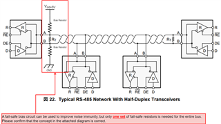
We are considering mounting an external fail-safe bias circuit for the THVD1510 as shown in the attached figure. Specifically, the purpose is the following two points.
(1) To prevent the receiver output from being undefined in the bus idle state as a fail-safe measure when open.
(2) To improve noise immunity by constantly flowing drive current to +200mV or more to fix the bus line logic to High even when all transceiver ICs connected to the bus line are in the receive state.

However, the number of units that can be connected to the bus is limited by the pull-up and pull-down resistor values, so we need to consider the constants. (The constants will be considered in the future.) If there are any adverse effects or concerns with this circuit configuration, please let us know.
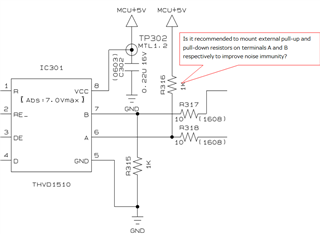
Regards,
Kagawa

  • The THVD1510 itself has fail-safe inputs and does not need external biasing resistors; the termination resistors will force an idle bus to 0 V, which is guaranteed to result in R = high.

    If you have receivers without fail-safe inputs anywhere on the bus, or if you want to improve the noise margin for an idle bus, then you can add these resistors. Please note that only one set of fail-safe resistors on the entire bus is needed.

  • Hi Kagawa,

    Clemen's is correct as usual.

    You can add the external fail safe resistors for additional noise margin. Main thing is you don't want too many nodes to have these resistors since it does introduce additional leakage current on the bus. RS485 limits leakage in terms of impedance to 375 ohms. As Clemens mentioned, its normally done only on one node (I usually see it on the driver but having it on a receiver node is okay as well).

    As Clemens pointed out as well, some devices like these have internal fail safe biasing where the Vth+ is a negative value so the external fail safe isn't required but will still help with noise margin during idle conditions.

    -Bobby

  • Bobby-san,

    From your response, I understand the following. Could you please confirm just to be sure if this understanding is correct?
    1. Basically, when using THVD1510, a fail-safe bias circuit is not necessary, but adding these resistors to improve noise margins will not affect communication operation.
    2. If the RS485 transceiver ICs of all devices connected via RS485 are THVD1510, a fail-safe bias circuit is not necessary.
    3. On that basis, a fail-safe bias circuit can be used to improve noise resistance, but only one set of fail-safe resistors is required for the entire bus.
    Regarding 3 in particular, please confirm whether the idea in the attached diagram is correct.


    Regards,
    Kagawa

  • 1. Basically, when using THVD1510, a fail-safe bias circuit is not necessary, but adding these resistors to improve noise margins will not affect communication operation.

    Correct, the fail safe bias circuit has a minimal affect on communication. Your resistor value should not be lower than 375 ohms (RS485 standard for leakage current)

    2. If the RS485 transceiver ICs of all devices connected via RS485 are THVD1510, a fail-safe bias circuit is not necessary.

    Correct. Vth+ in these devices are negative which should force R to be HIGH during an open or idle condition (assuming noise from the environment is low).

    3. On that basis, a fail-safe bias circuit can be used to improve noise resistance, but only one set of fail-safe resistors is required for the entire bus.
    Regarding 3 in particular, please confirm whether the idea in the attached diagram is correct.

    Correct, you could also place it on the furthest receiver node to the right. Usually its on one of the termination resistor nodes, doesn't matter which one.

    -Bobby