


Part Number: SN75HVD11
Tool/software:
Hello experts
Hope this finds you well.
How to understand VIT+、VIT-、Vhys in datasheet please?
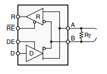
Please tell us what voltage the TTL level output (R in the following figure) changes after receiving with the Receiver. Specifically, what is the voltage of the differential input signal (a and B in the following figure)?
Regards,
Jieyu Zhou


