


Tool/software:
Hi,
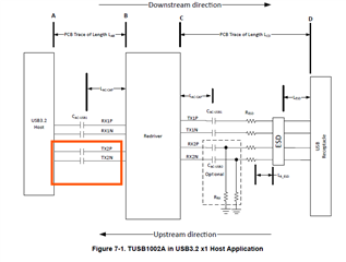
I would like to confirm what AC cap should be used for TX to host.
As the USB3.2 standard and CPU (host) vendor recommend to use 330nF. But in TUSB1002A suggest to use 220nF.
Please clarify.
Thanks.
Tool/software:
Hi,
I would like to confirm what AC cap should be used for TX to host.
As the USB3.2 standard and CPU (host) vendor recommend to use 330nF. But in TUSB1002A suggest to use 220nF.
Please clarify.
Thanks.
