This thread has been locked.

If you have a related question, please click the "Ask a related question" button in the top right corner. The newly created question will be automatically linked to this question.

TPD12S521: Circuit Review

Part Number: TPD12S521

Tool/software:

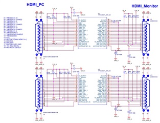
We are planning to make a board to extend HDMI between PC and Monitor.
- We will use 2m HDMI Cable on both sides.

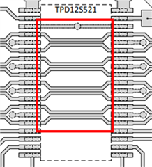
We are using TPD12S521 and designed the circuit by referring to the datasheet.

Please review the design and give feedback on the points to be aware of or areas that need to be modified.

We always use TI products and think your technology is the best.

I know you are busy, but please review it quickly.

Thank you.

  • Hi Sincheol,

    Thanks for reaching out and here's some suggestions:

    1. For the CE_remote_in pin of the upper chip, please add a 47 kOhm resistor, as you have added the R13 for the lower chip.

    2. Please add 10 kOhm pull-down resistor to GND_A from HOTPLUG_DET_OUT for both chips.

    3. A schottky diode is recommended between 3.3V and R11/R12, anode connected to 3.3V

    4. Romove R3 and R8, they are not needed.

    5. Please confirm you want 5V_out floating in your design.

    Please let me know if you have any other questions.

    BR,

    Ke Wang

  • Dear Ke Wang,

    Thank you very much for the detailed explanation.
    Thanks to you, I was able to make the correction.
    Excuse me, but I would like to ask one more question.
    The picture below is taken from the datasheet.
    Should I draw the PCB trace for the wiring inside the IC?

    Best Regards

  • Hi Sincheol,

    Yes you are right, those traces are on the PCB beneath the chip.

    Please make sure you follow the design rules for differential pairs.

    BR,

    Ke Wang