Other Parts Discussed in Thread: TUSB321,
Tool/software:
Hi,
For my current design, the TUSB320L is configured in GPIO mode (ADDR pin left NC) and as a DRP (PORT pin left NC).
I would like to confirm the following:
1. When both the TUSB320L and the external device are configured as DRP, how is the final role (UFP or DFP) determined?
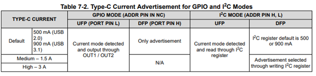
2. Is the current mode detection (via OUT1/OUT2) only available when operating as a UFP? Will there be no output on OUT1/OUT2 when acting as a DFP?
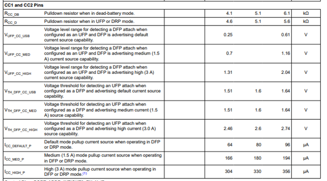
3. How is the advertised current determined — by the internal Rp or Rd resistors? In DFP mode, is it possible to advertise 1.5 A or 3 A current levels?
4. When connecting a smartphone to charge via USB Type-C, the charging process repeatedly starts and stops (intermittent charging).
I would like to know what the potential reasons for this behavior in my current setup could be.
Thank you for your support.