DP83TD510E-PODL-EVM: PoDL Implementation, TI Reference Design & Wurth Application Note Updates

Part Number: DP83TD510E-PODL-EVM
Other Parts Discussed in Thread: DP83TD510E

Tool/software:

Dear Ti Team,

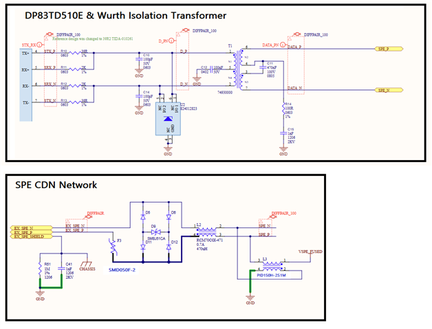
We are currently implementing an engineered PoDL solution without SCCP, most closely aligned with Class 14. For context, our design uses 48V DC at the PSE delivering 30W, and a minimum of 30V at the PD consuming 20W. Our current component selection for the SPE coupling and filtering network includes:

  • Ti SPE PHY: DP83TD510E

  • Wurth Isolation Transformer: 74930000

  • TDK PoDL Inductor: PID150H-251M

  • TDK Common Mode Choke: RCM70CGI-471

Our system is operational, successfully injecting PoDL and maintaining a stable SPE link over 250m of CAT6 UTP cable, with the PD powered via PoDL.

We’ve reviewed TI’s reference designs and PoDL application notes and have a few questions regarding recent updates:

  1. Transformer Update – Wurth 74930200 vs 74930000:
    We noticed the isolation transformer has been updated to PN: 74930200 in newer TI designs. This part does not appear on Wurth’s website, could you clarify if it is in pre-production? What was the reason for this change and is the 74930000 still considered suitable for PoDL applications?

  2. DC Blocking Capacitor Value Change:

    1. The center tap DC blocking capacitor on the transformer has been revised from 470nF to 100nF in recent designs. In addition some notes show 2 × 100nF, while Wurth’s PoDL filter design app note suggests 2 × 470nF per line. Could you explain the the reason for this change?

    2. Is this change only required if the new 74930200 is designed in or is this update required when the selected TDK DMI and CMC are used for PoDL, which essentially form an LC filter?

    3. Is this capacitor change also recommended for non-PoDL SPE designs when not provisioning the DMI and CMC?

  3. TX Resistor Value Change:
    We observed that the DP83TD510E SPE Tx resistors have been updated from 49.9Ω to 39.2Ω. What prompted this adjustment? Is this update only required for PoDL designs or also a requirement for non-PoDL designs or is this to compensate for the change to the new 74930200 Transformer?

  4. Polyfuse Protection on Connector Interface:
    In addition to the standard 4 steering diodes and TVS suppresion diode on the connector’s primary side, we are considering adding an SMD050F-2 polyfuse to protect against accidental high-voltage connections. Bench testing with a single series SMD050F-2 on the SPE_P line directly at the connector before the diodes and TVS show no obvious impact on link performance. Do you foresee any issues with this approach under different operating conditions or cable lengths?

See our design reference images below for context:

We appreciate your insights and guidance on these points to help us align our design with best practices and performance.

Best regards,


Daniel Haddad

  • Hi Daniel, 

    Glad to hear you were able to see stable performance over PoDL!

    Transformer Update – Wurth 74930200 vs 74930000:
    We noticed the isolation transformer has been updated to PN: 74930200 in newer TI designs. This part does not appear on Wurth’s website, could you clarify if it is in pre-production? What was the reason for this change and is the 74930000 still considered suitable for PoDL applications?

    74930000 is still recommended for these designs. The other parts ion the schematic are also parts that have been tested with our PoDL design. I am not sure if the 74930200 is public or not, but I was able to find it mentioned in the following link on page 45. Regardless, both of these parts have been validated and you can use either one in this application. 

    DC Blocking Capacitor Value Change:

    1. The center tap DC blocking capacitor on the transformer has been revised from 470nF to 100nF in recent designs. In addition some notes show 2 × 100nF, while Wurth’s PoDL filter design app note suggests 2 × 470nF per line. Could you explain the the reason for this change?

    2. Is this change only required if the new 74930200 is designed in or is this update required when the selected TDK DMI and CMC are used for PoDL, which essentially form an LC filter?

    3. Is this capacitor change also recommended for non-PoDL SPE designs when not provisioning the DMI and CMC?

    TI recommends using 100nF because this value has been tested and validated with our design. We also recommend using these values with either of the transformers being used.

    TX Resistor Value Change:
    We observed that the DP83TD510E SPE Tx resistors have been updated from 49.9Ω to 39.2Ω. What prompted this adjustment? Is this update only required for PoDL designs or also a requirement for non-PoDL designs or is this to compensate for the change to the new 74930200 Transformer?

    This change is to compensate for the impedance added on the line due to added parts. Usually these resistors function to match the cable impedance, which is usually 100Ohms differential, which is ~50Ohms per line. In this case, we use a slightly smaller value to ensure that the additional components impedance is accounter for and the correct amplitude is reached on the MDI output.

    Polyfuse Protection on Connector Interface:
    In addition to the standard 4 steering diodes and TVS suppresion diode on the connector’s primary side, we are considering adding an SMD050F-2 polyfuse to protect against accidental high-voltage connections. Bench testing with a single series SMD050F-2 on the SPE_P line directly at the connector before the diodes and TVS show no obvious impact on link performance. Do you foresee any issues with this approach under different operating conditions or cable lengths?

    Unfortunately, we have not tested anything similar to this application on our device, and cannot recommend to add this on the MDI line.

    Best,

    Vivaan

  • Hi Vivaan,

    Thanks for your quick reply and the details you shared.

    I’d like to better understand the rationale behind the recommendation to use a 100 nF DC blocking capacitor in the TI PoDL reference design, particularly in the context of the Wurth 74930000 transformer.

    The original Wurth application note (ANP085b, pages 6–7) specifies a 470 nF capacitor, noting that while 100 nF meets the minimum IEEE 802.3cg requirements, simulations and measurements showed that 470 nF achieves better droop performance - specifically 8.3%, well within the 10% limit defined in Clause 146.5.4.2.

    I suspect this choice was influenced by the 74930000’s 350 µH inductance, whereas the TI reference design uses the 74930200, which has a higher inductance of 600 µH. Wurth also notes that increasing transformer inductance is another way to reduce droop, but using a larger capacitor is more space-efficient and cost-effective.

    Given this, would it be more appropriate to retain the 470 nF capacitor when using the 74930000, to ensure droop remains well within spec? Or are there other consideration that makes 100 nF preferable even with the lower inductance transformer?

    Appreciate your insights.

    Best regards,
    Daniel Haddad

  • Daniel, 

    I understand the choice made by Wurth to be able to use a 470nF capacitor, but unfortunately we have not tested this ourselves. I believe we only tested the 100nF since that was what was defined in the standard.

    That being said, it is not a hard requirement to use 100nF and using 470nF wouldn't be cause for concern. It looks like Wurth does have some data showing that 470nF results in better performance, in which case it may be more appropriate to use that value in your design if even better droop performance is wanted. Regardless of this choice, the PHY would be able to perform as intended

    Best,

    Vivaan

  • Hi Vivaan, thank you for your assistance. We will run some tests and lock in the preferred value. We appreciate your support. 

    Best Regards, 
    Daniel