LMH6574: LMH6574 strange behaviour

Part Number: LMH6574


Hi all

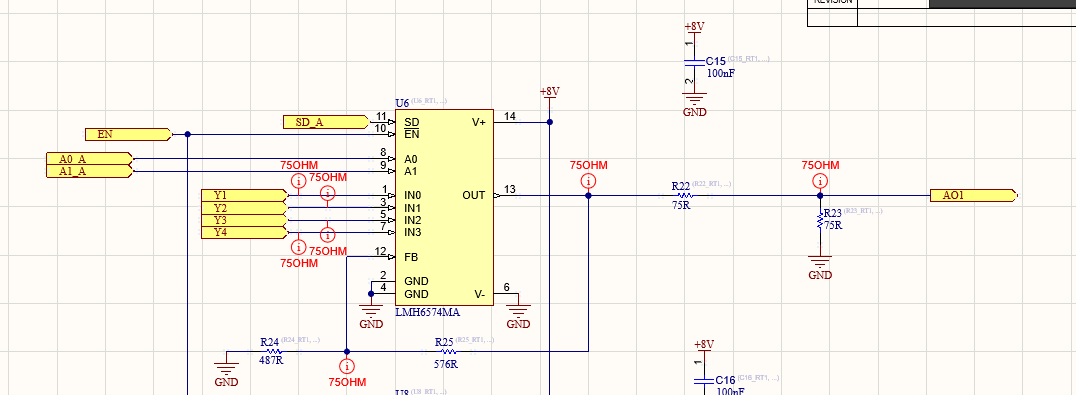
I've designed a video switcher based on the LMH6574 part.

The amplifier is supplied by 8V singe supply.

Control pins (A0,A1,EN,SD) controlled using 3.3V from a MCU.

The issue I have is that the output signal seems to be unrelated to the address I specify via A0,A1 pins. No matter which channel I choose, the output signal comes from the first input pin. And the signal itself is very bad. See pictures.

EN and SD pins kept low.  

Schematic:

Schematic.png

Input signal (10x probe):

In.jpg

Output signal (10x probe):

Out.jpg

What is the reason for such situation? Is that reasonable?

UPD: It seems that Ax, SD and EN pins work when I short them to 8V (supply pin). I do not understand why they do not work with 3.3V. So I suspect that powering the device with single supply source is the issue... But can I get some qualified explanation "why"?

  • Hi,

    Thanks for sharing the update. Just to confirm, are you saying the device now switches through different channels and works fine when A0 and A1 are connected to 8V and EN and SD are ground? With the EN and SD to ground I would assume A0 and A1 would work with 3.3V.

    Best Regards,

    Ignacio

  • When instead I use 8V to control Ax, SD and EN it responds to the commands. But it is not "working fine", I mean the output signal is strange somehow, like it simply has cut everything below 1V.

    I tried your suggestion earlier, the device is not responding to 3.3V control signals (even when EN and SD are tied to GND).

    I suspect that device is not able to operate from a single supply... but why then in datasheet is clearly stays it can?

  • Hi,

    This is interesting as I am not sure why the control pins would not be referenced to GND as this is what you set for the GND pins. Could you share the input signal you are setting at the input pins.

    Best Regards,

    Ignacio

  • Hi Ignacio,

    Exactly my thoughts.

    The first scope picture in my first post is an input signal. The second is an output signal.

  • Hi,

    Sorry I didn't notice you had input and output. From looking at the input signal, I think the circuit might be violating the input range of the device. Since it is in a single supply configuration, we always recommend offsetting the input to mid-supply to ensure the input range of any device is not violated. The input signal seems to be centered around ground which would be violating the input range of the device. 

    Best Regards,

    Ignacio

  • I changed the supply to +/-3.3V instead of single +8V supply and now it works as expected. The address can be changed using 3.3V signal. 
    So, the bottom line here is that the device in NOT able to operate from a single supply and maintan the specs from datasheet. I would really recommend to update the documentation on the part.