TPS36-Q1: TPS36CA39EACDDFRQ1 || Interfacing to AM2612 MCU

Part Number: TPS36-Q1
Other Parts Discussed in Thread: AM2612, TPS36

Hello TI support team,

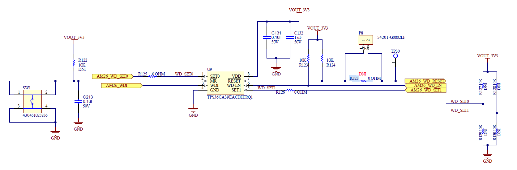
We are using TPS36CA39EACDDFRQ1 -Voltage Supervisor with Precision Window Watchdog Timer, RESETn (AM26_WD_RESET) pin of TPS36 is connected to WARMRSTn pin of AM2612.

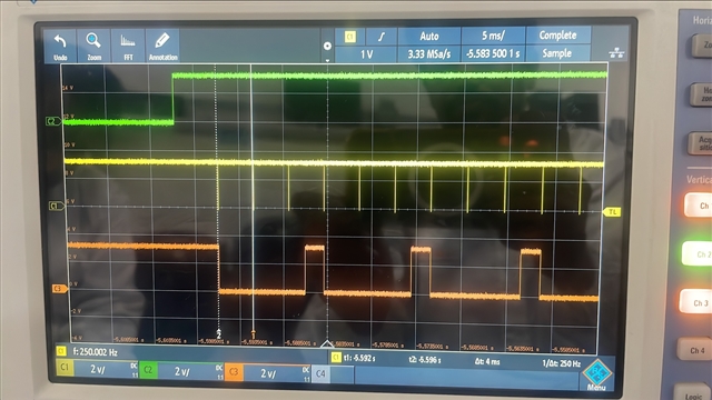
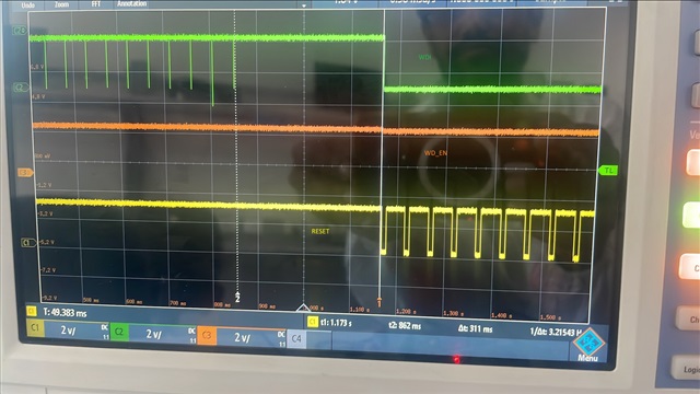
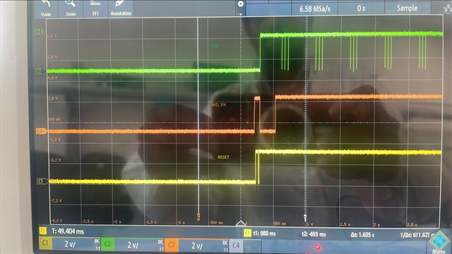
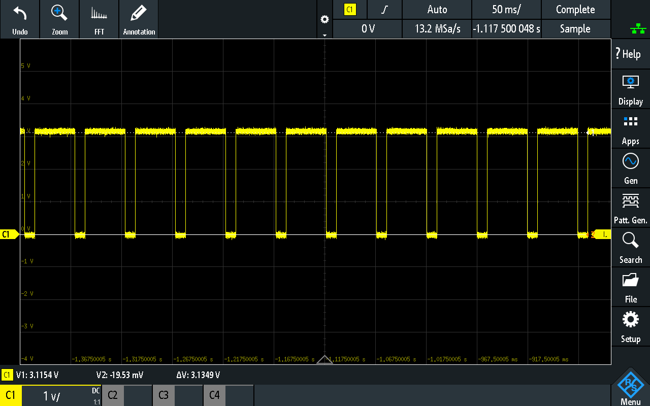
When we tested the TPS36 watch dog in manual mode by asserting the MR pin, the RESET out is toggling and same is observed even with the soft control with the timings for pins WDI,SET0,SET1 then also RESET out is toggling.

Due to above issue, MCU is not coming out of reset.

Please find the schematic and also attached the MR pin and RESET out waveforms in the attachment.
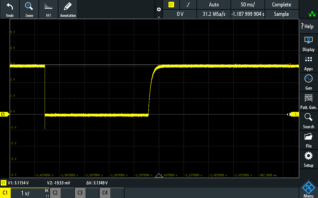
MR_Signal.png

TPS36_watchdog.pngRESET_OUT.png

Thank you,

Anand

  • Hi Anand,

    Based on your description, the device is not detecting any input. Looking at the RESET output the device is functional, which is a good start. To troubleshoot, are you able to replace C213 with a 10kohm resistor, this will create a voltage divider with the internal MR pull-up resistor which will cause the MR input below the VIL. The expected result is the RESET to be held LOW. If this is observed, there may be an issue with the switch that your are using. 

    Also, just to confirm, the SETx is not able to change the window ratio or disable the watchdog? Based on the waveform and part being used, SET0=LOW and SET1=LOW, is that the intended configuration? Does driving WD_EN=LOW disable the watchdog?

    My immediate impression of your issue is that the AM2612 may not be sending a WDI pulse fast enough at start-up, causing a reset to assert preventing the AM2612 from fully powering up. Having the SETx pins both pulled-up, extending the open window, may also help if this is the issue. 

    Jesse 

  • The above option is checked by replacing the C213 with 10kohm , The RESET signal is held LOW. Also, voltage at MR input is  Approx~= 0.3V

  • Hi Mallikarjuanreddy,

    Thank you for the confirmation, moving forward, you may put the C213 back now that we confirmed that MR functionality is working. This portion of the inquiry may be due to the switch being used. 

    Jesse 

  • Hi Jesse,

    Ok, now we have replaced the C213.

    Now we are configured the SET0 - Low, SET1 - High 

    and sending the WDI pulse within 5 msec,

    Still the RESET out of TPS is toggling every  Appr0x 10 msec

    Please do check and suggest. 

  • Hi Mallikarjuanreddy,

    Just to confirm, the green signal is the device VDD, the yellow is the WDI input pulse, and the orange is the RESET assertion. Is that correct?

    In the configuration with SET0 = LOW and SET1 = HIGH, the watchdog open time ratio is set to 4. As a result, the open window time is 20ms * (4-1) = 60ms and the close window time is 20ms. Sending a pulse within 5ms seems to be triggering an early fault as there should be at least a 20ms pause between each WDI pulse.

    For the configuration with SET0 = LOW and SET1 = HIGH, could you please try to send a WDI pulse every 50ms? This way, the 20ms close window would have surpassed, and the pulse will be provided directly in the middle of the 60ms open window.

    Best Regards,

    Andrew Li

  • Hi Andrew Li,

    Thanks for the clarification, I will try this and update.

    ( Andrew Li, said :  a result, the open window time is 20ms * (4-1) = 60ms and the close window time is 20ms.)

    Can please let me know where do i get this timing parameter in the datasheet. 

  • Hi Andrew,

    I have re-checked my code there was mistaje in my selection of SETx pins it was set to SET0 = LOW and SET1 = LOW.

    Now i have modified and

    1. set, SET0 = LOW and SET1 = HIGH

    2. WDI pulse sending around the 50 msec.

    3. Now RESET is toggling for few msec and Stay HIGH as expected.

    But now the issue is when we stop the WDI pulse, and set WDI to LOW, now RESET goes LOW for few mese approx. 150msec and start toggling at 50 msec. MCU is not rebooting until power cycle.After power cycle it works as expected.

    We have connected the RESET out to warmRESET of MCU.

    MCU code has to disable WDEN on reset.

    void TPS36_init(void)
    {
        /* WDI idle high */
        GPIO_pinWriteHigh(TPS36_WDI_GPIO_BASE_ADDR, TPS36_WDI_PIN);

        GPIO_pinWriteLow(TPS36_SET0_GPIO_BASE_ADDR,  TPS36_SET0_PIN);  /* SET0 = 0 */
        GPIO_pinWriteHigh(TPS36_SET1_GPIO_BASE_ADDR, TPS36_SET1_PIN);  /* SET1 = 1 */

        /* Disable watchdog initially — host will enable after boot */
        GPIO_pinWriteLow(TPS36_WDEN_GPIO_BASE_ADDR, TPS36_WDEN_PIN);
        gWatchdogEnabled = false;

     
    }
  • Hi Mallikarjuanreddy,

    The close window time of 20ms is denoted by the part number of the device and this decoder image below:

    For TPS36CA39EACDDFRQ1, the bolded E after the 39 denotes that the 20ms close window, and with SET0 = LOW and SET1 = HIGH, the open window follows the equation below:

    t_cw * (n-1) where n = 4 due to SET0/1. Thus 20ms * (4-1) = 60ms = open window time.

    Best Regards,

    Andrew Li

  • Hi Mallikarjuanreddy,

    I'm not sure if I fully understood your issue. Here is my understanding:

    • With SET0 = LOW and SET1 = HIGH set properly and WDI pulse sending around 50ms, the TPS36 functions as expected.
    • When the system stops sending WDI (the system lets the watchdog timer assert a late fault) the RESET output asserts for 150ms. Is this correct, or what do you mean by "start toggling at 50ms"?

    In the second situation, do you mean that the MCU is not rebooting even after the system applies WDI input again? An oscilloscope capture would be very helpful here.

    Best Regards,

    Andrew Li

  • Hi,

    • With SET0 = LOW and SET1 = HIGH set properly and WDI pulse sending around 50ms, the TPS36 functions as expected.
      • YES correct it functions as expected.
    • When the system stops sending WDI (the system lets the watchdog timer assert a late fault) the RESET output asserts for 150ms. Is this correct, or what do you mean by "start toggling at 50ms"?
      • Yes, we want to test TPS functionality so, we stopped sending the WDI, So, system timer asserts the for fault.
      • RESET signal toggling at 50 msec 

    I have attached the waveform when stop sending WDI. During this state MCU is not coming out of reset.

    Also, i have attached waveform when Power Cycle is Done

    .

    MCU Needs around 150 msec to start application including the RBL and SBL boot time.

    Can you check and update. Still any further information is needed

  • Hi Mallikarjuanreddy,

    Let me double check with the team about your issue and I will respond tomorrow.

    Best Regards,

    Andrew Li

  • Hi Mallikarjuanreddy,

    Thanks for your patience.

    My understanding is that once the last WDI signal is sent, the system timer is asserting after 50ms. The device asserts for 10ms as denoted by the output assert time in the part number, then the cycle starts again with the close/open windows. The problem you are facing is that the MCU needs around 150ms to boot up, and the current open window is too short to allow it to boot up properly. Is this correct?

    If so, my recommendation would be to increase the watchdog open window time with SET0 = SET1 = HIGH to use the maximum watchdog open time ratio of 16 for this device. This way, the open window will be 20ms * (16-1) = 300ms. The MCU should have plenty of time to reboot this way.

    Best Regards,

    Andrew Li

  • hi 

    I have changed the SET0 an SET 1 HIGH.

    Now open window is 300 msec.

    As mentioned, when the WDI assert stops, TPS RESET out starts the after 300msec. Still the MCU is not getting out of reset 

    1. Attaching the waveform when WDI pulse assert RESET behavior

    2. When PORz Assert RESET behavior

  • Hi Mallikarjuanreddy,

    Is the SETx configuration driven by the GPIO of the MCU. Looking at the image below, the watchdog time looks like it is still set to SETx=0.

    You may want to use resistor pull-up make sure the timing is proper when there is no GPIO driving.

    If pull-up resistors are not an option, you may want to switch over to TPS36CD40EACDDFRQ1, which has a 1sec start-up delay and a voltage threshold of 3V vs 2.95V of the current device. 

    Jesse 

  • Hi,

    Thanks for the TPS36CD40EACDDFRQ1, suggest we will check this also in future.

    as of now for first iteration, it works with following changes.

    We have removed the Pull-up for WD_EN and control through the MCU.

    Now it's working as expected. MCU is rebooting when the WDI stop sending the pulse.

  • Good to hear, please let us know if additional help is needed here. One thing I would like to bring up about your current solution, since you have the enable driven by the MCU, in cases where the MCU fails and the GPIO goes high impedance, disabling the watchdog, the fault may not be detected

    Jesse