Because of the holidays, TI E2E™ design support forum responses will be delayed from Dec. 25 through Jan. 2. Thank you for your patience.

This thread has been locked.

If you have a related question, please click the "Ask a related question" button in the top right corner. The newly created question will be automatically linked to this question.

Cascading LMH0366 external clocks

Other Parts Discussed in Thread: LMH0366

Hi ,

Can a single cmos oscillator  be used as the 27 MHz reference for multiple reclockers by connecting the XTAL_OUT output of one reclocker to the XTAL_IN input of the next, propagating the 27 MHz reference signal through a cascade of reclockers?

The LMH0366 datasheet states that it can be done by driving the  XTAL_IN pin of the first reclocker with a crystal oscillator or 2.5V LVCMOS clock signal ????.

The picture below is that of the 27MHz signal at the XTAL_IN pin of the first reclocker . The next picture is that of the signal at the XTAL_OUT pin of the first reclocker.  

How can we make the signal propagate down the cascade ? Are  specific register settings required to enable clock cascading??

We  are using the LMH0366 in  SPI MODE. 

REF_CLK_DET = 1 at the first reclocker and 0 at the second reclocker.


Regards.

Hein

  • Greetings,

    Looking at the XTAL output, there seems to be duty cycle distortion which lengthens the negative and positive pulses alternatively. By the time the signal reaches the input of the other devices there is not enough signal amplitude to cause the crystal circuit to toggle. 

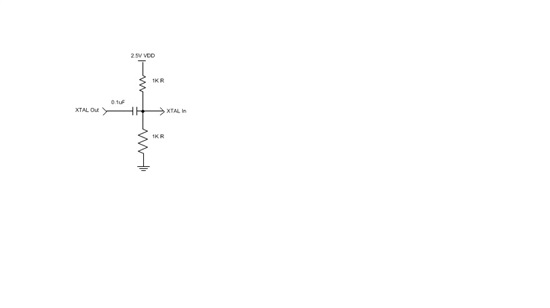
    Could you please try AC coupled with 1KΩ terminations as shown in the image below. This circuit goes at the output of the crystal oscillator and between XTAL out from one device to XTAL in to another device.

    Given this circuit, we are AC coupling and isolating the common mode voltage of each stage. For this circuit configuration the mean voltage at the XTAL IN input to each reclocker is approximately the nominal value of VCC/2. The 1KΩ terminations in combination with AC coupling are sufficient to constrain the common mode voltage at the input to each reclocker stage so that stable operation is maintained throughout the 27 MHz reference daisy-chain. Smaller termination Resistors would also work but would draw more static DC current from the power supply.

    The placement of the coupling capacitor and the voltage divider resistors on the board is not critical as long as the transmission line between the reclockers is kept electrically short. A good rule of thumb for the length of this transmission line is the same as the rule of thumb for the length of an unterminated stub on a PC board. The length of the transmission line in inches (L) should be less than or equal to the rise time of the signal in ns (TR). For the 27 MHz reference, TR ≈ 4ns, so we should design for L ≤ 4”.

    Regards,,nasser