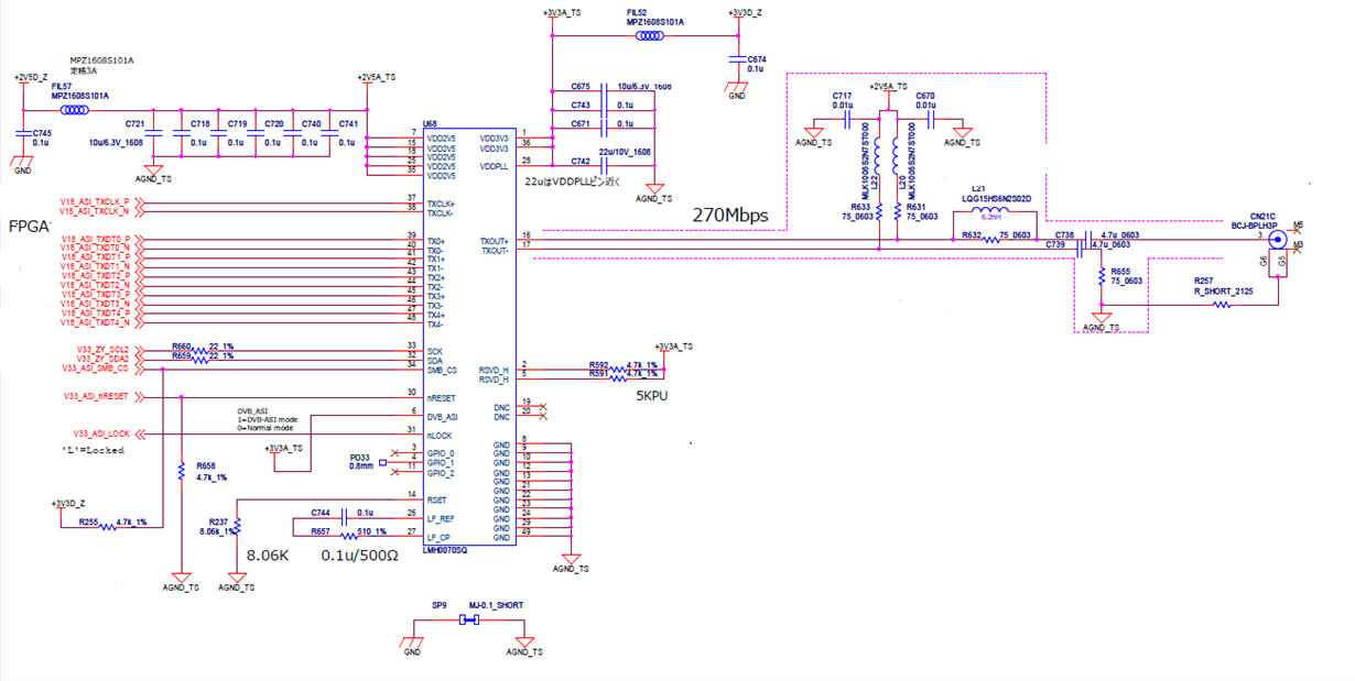
I am trying to outout DVB-ASI signals of MPEG-2 transport stream through LMH0070
using its DVB-ASI mode, but DVB-ASI stream analyzer connected to DVB-ASI output terminal
did not detect MPEG-2 transport stream.
I cheked registers via SMB bus and found a few questions. let me know if someone knows
the root cause of these problem.
1) My board connects 3.3V power line to DVB_ASI pin of LMH0070.
I expect Mode register (address 0x21, bit [1:0]) would be "3" (DVB-ASI mode),
but it is "0" instead. Is there any problem in the schematics of the board?.
Also, Mode register did not change after I wrote "1" to RESET register (address 0x01, bit[0]).
registers values after power up
0 1 2 3 4 5 6 7 8 9 a b c d e f
00: ae 00 05 05 04 00 00 01 03 bc 01 1c 01 bc 01 bc
10: 01 bc 01 00 00 bc 01 62 00 00 00 00 00 fe 04 00
20: 00 00 00 00 00 00 3f 00 04 00 0f 00 00 80 00 38 <<< 0x21 bit[1:0] Mode register=0
30: 62 02 00 58 06 00 00 00 00 00 00 00 00 00 00 00
40: 55 00 00 37 10 0f 38 40 02 7d c4 1a 80 03 1c 57
50: 00 00 00 00 00 00 00 00 00 00 00 00 00 00 00 00
60: 0c 00 00 00 00 00 00 20 20 03 00 00 00 00 00 00
70: 00 00 00 00 00 00 00 00 00 00 00 00 00 00 00 00
80: 00 00 00 00 00 00 00 00 00 00 00 00 00 00 00 00
90: 00 00 00 00 00 00 00 00 00 00 00 00 00 00 00 00
a0: 00 00 00 00 00 00 00 00 00 00 00 00 00 00 00 00
b0: 00 00 00 00 00 00 00 00 00 00 00 00 00 00 00 00
c0: 00 00 00 00 00 00 00 00 00 00 00 00 00 00 00 00
d0: 00 00 00 00 00 00 00 00 00 00 00 00 00 00 00 00
e0: 00 00 00 00 00 00 00 00 00 00 00 00 00 00 00 00
f0: 00 00 00 00 00 00 00 00 00 00 00 00 00 00 00 00
2) I tried to change Mode by the following register write sequence and found Mode
register was set to "3". but still DVD-ASI stream analizer did not detect MPEG-2 transport
streams. so I think I failed to change operation mode of LMH0070.
Is this sequence correct to change Mode?
address data
0x21 0x3 (Mode)
0x22 0x1 (DVB_ASI Override)
0x26 0xBF (channel reset)
3) Input pins TXCLK+, TXCLK-, TX[4:0]+, TX[4:0]- are connected to FPGA.
I assume polarity of those input signals are "positive".
Attached Simulation wave form shows signals of those input pins when
Null packet (0x47 0x1F 0xFF 0x10 0xFF 0xFF ...) is put into LMH0070.
Is there any problem regarding to this wave form?


