Part Number: SN65HVD1782
Other Parts Discussed in Thread: SN65HVD1781
I am using TI's SN65HVD1782DR RS-485 transceivers in an industrial wall control design that I am working on.
We would like for the two RS-485 interfaces on the wall control to be as robust against ESD, surge, short circuits, and mis-wires as possible.
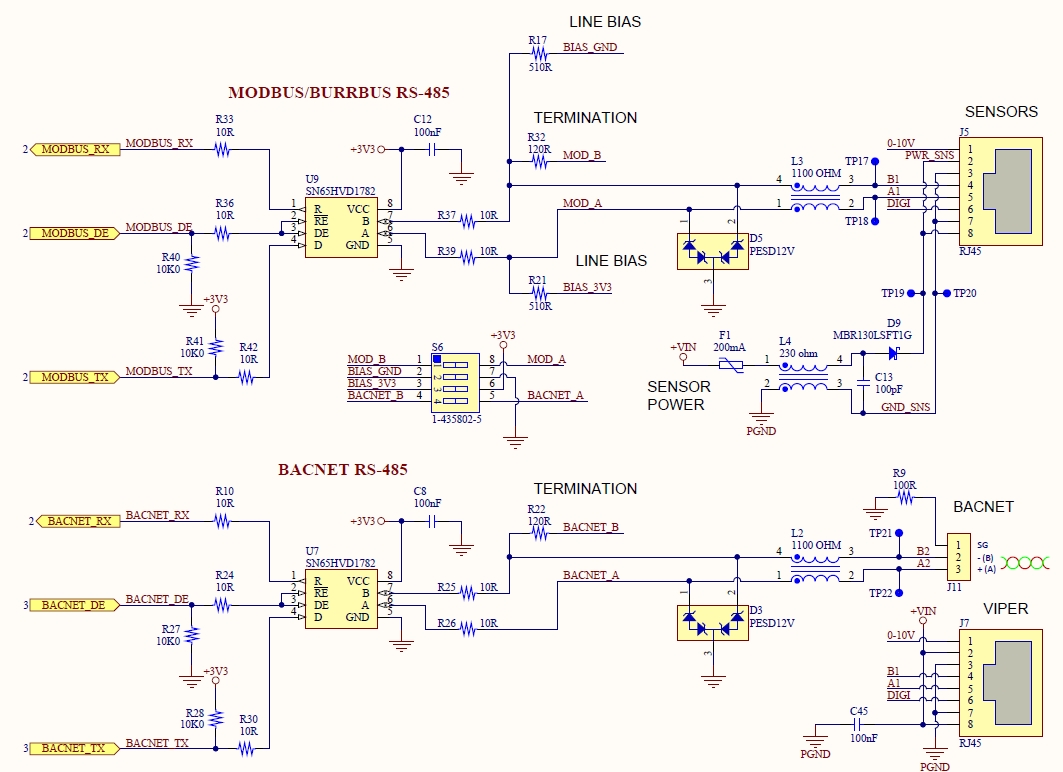
One of the scenarios that we would like to survive is when one of the A or B lines of a RS-485 interface is shorted to ground, and power (+24VDC, 250mA) is applied to the wall control in reverse polarity (See connector J8, pins 2 and 3 in attached power supply schematic). This could be a very real situation because our users will be making their own CAT-5 cable terminations that plug into connector J7 of the RS-485 schematic. It is possible that they could have ground connected to A or B, as well as +VIN (+24VDC) and ground backwards when they terminate the cable with an RJ-45 connector.
When I connected the PCB in this manner yesterday, I damaged the SN65HVD1782 that had it's A line shorted to ground (U7 in attached RS-485 schematic). I did notice that my bench-top power supply (programmed for +24VDC, 250ma current limit) dropped to approximately 7 volts and had reached it's current limit, so there was definitely a low impedance return path somewhere. I left this configuration connected for approximately 20 to 30 seconds.
So what is confusing me about all of this is that the datasheet for this part says on Page 4, Table 7.1 that the maximum voltage at the A, B pins of the 1782 is -70V to +30V. It then says that the Transient overvoltage pulse through 100 ohm per TIA-485 is -70V to +70V.
I don't understand the timing involved in these two seeming contrasting specs. For the Voltage at bus pin spec, how long can these voltages be connected to the A, B pins? Furthermore, the typical Application schematic on page 21 of the datasheet shows 10 ohm series resistors on the A and B lines, so where is the 100 ohm resistance referred to in the Transient overvoltage pulse spec coming from in Absolute Maximum Ratings? Also, there is no time specified for the transient overvoltage pulse.
It seems to me, that in the intentionally wrong wiring scenario that I tried, I was only applying +24VDC to the ground pin of the SN65HVD1782, and grounding the A pin through a 10 ohm resistor. This -24VDC applied to the A pin certainly seems within the voltage tolerances stated in the datasheet.
I have ordered some samples of the SN65HVD1781 and SN65HVD1782 so that I can try to repeat this experiment to see if I get the same results. But before I do that, I want to better understand the part's datasheet to make sure I'm not subjecting the part to abuses that it was never intended to survive.