This thread has been locked.

If you have a related question, please click the "Ask a related question" button in the top right corner. The newly created question will be automatically linked to this question.

SN65HVD231: SN65HVD231 used 3.3V CAN have problem.

Part Number: SN65HVD231

Hi,

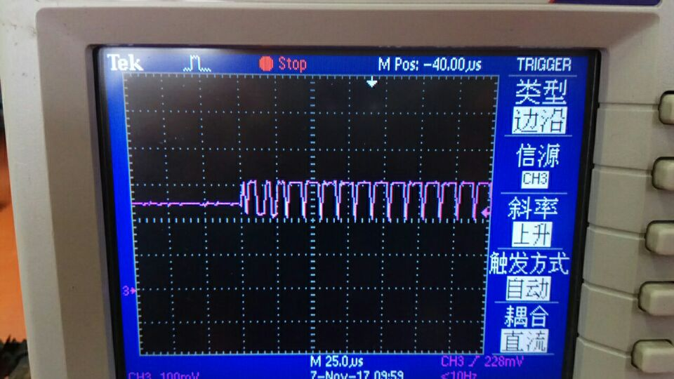
We use the SN65HVD231 in T-BOX,we find CANH waveform like below @ 3.3V CAN, but we use 5V CAN isn't any problem.

set up on car connect with other 5V CAN. What caused it?

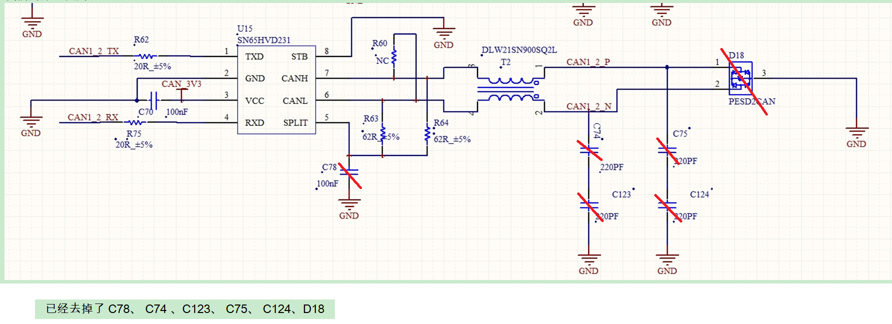
circuit as below, and del C78、 C74 、C123、 C75、 C124、D18 also could not be improved.

Many thanks.

 I used 3.3V CAN in 5-V CAN Systems. when bus impedance is 120ohm, the OBD can receive T-Box signal.

but when bus impedance is 60ohm, the OBD can't receive T-Box signal.

What causes the OBD receives signals to fail?


  • Hi Wu,

    if I understood correctly, you are using a CAN transceiver at 5V which is meant to be used at 3.3V and the part still works. Once you connect it on the car with another CAN device, then it fails.

    Could you please explain what signals are you measuring and if they are correct or not? Does the problem only show on the CANH line?
    If you could tell me a bit more information about how and what do you expect from the transceiver, then I could try and formulate some thoughts.

    Also, from the schematic I can't understand if you tried to implement those capacitors but you didn't like the result of using them or they are originally not meant to be designed in your application.

    Please let me know.
    Best regards,
    Adrian
  • Hi Adrian,
    Update my question.
    My question is I used 3.3V CAN in 5-V CAN Systems. when bus impedance is 120ohm, the OBD can receive T-Box signal.
    but when bus impedance is 60ohm, the OBD can't receive T-Box signal.
    What causes the OBD receives signals to fail?
    thanks.
  • Hi Wu,

    thank you for the explanation.

    The OBD works in the first scenario since the termination of the network is the right one, that is 120ohm. This is a typical termination that you put at each end of the bus, as you showed in your schematic, and it's required by the ISO11898 Standard; the result will be that of preventing reflections.

    The other possibility to that termination would be the split termination, that is two 60 ohm resistors with a capacitor in the middle of these resistors to ground. You can see it in the following picture.

    Now my question is, do you use only one 60ohm resistor or two like the standard split termination?

    Having a smaller impedance at the termination will generate higher currents in the line, which the transceiver will have to generate. If it's not able to source that current, the voltages might decrease to the point where they are not meaningful.

    Let me know if this clarifies your idea.

    Thank you and best regards,

    Adrian

  • Hi Adrian,
    For bus impedance balance, all products on bus aren't connect any impedance.
    3.3V T-Box is Standard Termination.
    Look my schematic, R60, R63, R64 no connect any resistance.
    Thanks.
  • Hi Wu,

    so none of the device present on your system have an internal termination, except for the T-BOx?

    Could you confirm to me if your system looks like the one in the following picture? That is, multiple devices connected to the bus line with two resistors of 60ohm, one at each end of the line.

    Could you please let me know which value is the standard termination inside the TBOX?

    I would first suggest to understand what's the impedance value that you see on the bus line. The issue might be with a too high or too low value. You could directly measure the impedance of the bus by using a multi meter across CANH and CANL. Should be an easy measurement, so please let me know which is the value of the resistance on the bus.

    I have a question about the schematic: did you disconnect the resistors R60, R63, R64 after you saw the issue with the OBD port or even before the issue they weren't connected?

    Thank you for your time.

    Best regards,

    Adrian

  • Hi Adrian,
    update my picture.
    the system has another T-Box, like instrument.
    Now T-Box standard termination not connect any resistance, because for the bus balance.
    The bus impedance is 60ohm, two 120ohm parallel.
    R60, R63, R64 not connect any resistance.
    This issue occur reason is when impedance of bus is 60ohm, but impedance in 120ohm is normal work.
  • Hi Wu,

    I would kindly ask to you to redraw on a new post your system on both situations: the values of termination that makes the system work plus another one with the value of the termination that makes the system fail. This at least would clarify the system level.

    • I totally understand the schematic part now, the resistors aren't connected as you said, but they shouldn't be the problem. I can give you a better thought once you'll explain the complete system, failing and working ones.
    • Regarding the first waveform of the CANH signal that you posted, it is correct to have those voltage values since the device is operating in a asymmetrical way.
    • Only having the CANH signal plotted doesn't really tell much of what is going on with the behavior of the device. Could you please plot the same kind of waveform but also for CANL, Receiver and Driver? This way I can understand also if the problem happens only when receiving or sending data.
    • Does this issue happen also when other data rates are applied? Have you tried to use a slower data rate? Usually it helps to read the signals.

    Please let me know if this makes sense to you. I hope to hear your reply on this.

    Best regards,

    Adrian