


Hello,
i have taken the following eye-diagram
(i already know that my design has an issue with high capacitance and high series resistance but thats not relevant right know)
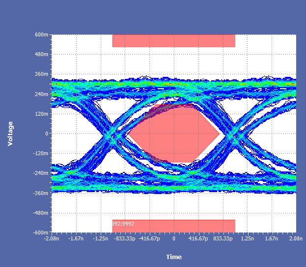
This is the diagram with no manipulation of the TUSB215, but you can already see two destinct rising edges
and two separated top and bottom Voltage levels.
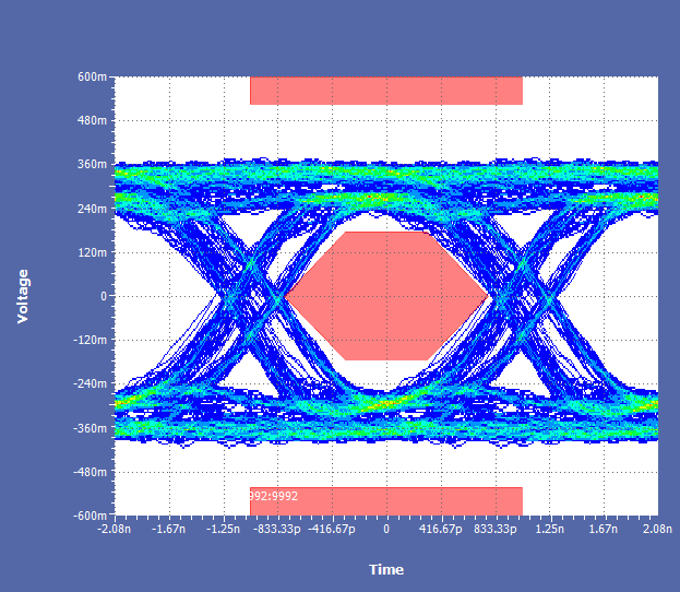
after using the signal conditioner the seperated signal paths get even worse which is not a surprise.
So my question is if anyone knows what exactly can cause such a signal.
To me it seems to be an timing issue but i cant tell whats causing it.
Thank you for the help,
Tim
