


Hello,
We are using AM26LV32E for several of our designs since the output state is guaranteed when the inputs A and B are left floating.
We observed (with multimeter and scope) the following voltages when the inputs are left floating with a supply of 3.3V:
- 2.4V on the A input
- 2.3V on the A input
Those voltages seem quite repeatable after testing on several parts of different batches. I wanted to know how predictible those voltage were, thus I simulated with LTPSICE the input circuit provided in Section 8.2 of the datasheet (page 8). Since I don't have the characterstics of the active components, I used 1N4148 diodes, and 2N222 / 2N2907 bipolar transistors, as shown on the figure below for the B input (200k resistor to Vcc instead of GND for A input):
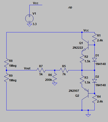
The result is different from the measurement, I find:
- 1.71V for the A input
- 1.59V for the B input
This is actually the order of magnitude that I would expect (half of the supply voltage) since the input circuit is relatively balanced.
Is the input circuit provided in the datasheet correct, or maybe the characteristics of the active components are much different from the ones I have simulated ?
Is it normal in practice to obtain 2.3V (B inputs) and 2.4V (A inputs) when the pins are left floating ?
Thank you for your help.
Thomas
