Because of the Thanksgiving holiday in the U.S., TI E2E™ design support forum responses may be delayed from November 25 through December 2. Thank you for your patience.

This thread has been locked.

If you have a related question, please click the "Ask a related question" button in the top right corner. The newly created question will be automatically linked to this question.

SN65HVD1476: Unpowered driver output impedance

Part Number: SN65HVD1476

Figure 29 of the SLLSEJ8D version of the datasheet appears to indicate that the output impedance of the driver stage (Y & Z) would be high even when the device is unpowered. The ABS max ratings suggest this would be true for voltages between -13V and +16.5V.

Please confirm there are no internal sneak paths for current to flow into the device through the output when Vcc is = 0 V.

  • Steve,

    Yes, I can confirm this. You can find the expected leakage current in the "bus input current" spec, which lists VCC = 0 V as a test condition. (This is a common feature among modern RS-485 transceivers since maintaining a high-Z input when unpowered is important in allowing nodes to be installed to active networks without disrupting communication and to allow flexibility in power sequencing across the network.)

    Regards,
    Max
  • Max -

    The bus input current spec (Ii) is 333uA - does that apply to both the driver (Figure 29) and the receiver (Figure 28). We are concerned more with driver - is that much less than 333uA with 12V applied?
  • Steve,

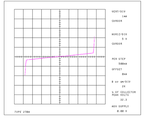
    The spec is general in applying to either one, but in general the leakage into an inactive driver is significantly smaller than the leakage into a receiver (due to the resistance network shown in the input equivalent circuit diagrams you mentioned).  To illustrate this better, here is a curve trace of the "A" input ("B" looks the same):

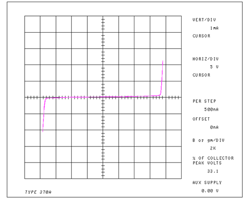
    Here is a curve trace of the "Y" output ("Z" looks the same):

    Best regards,
    Max