This thread has been locked.

If you have a related question, please click the "Ask a related question" button in the top right corner. The newly created question will be automatically linked to this question.

DS15BA101: DS15BA101

Part Number: DS15BA101
Other Parts Discussed in Thread: DS15EA101,

My customer use DS15BA101 + DS15EA101, some of DS15EA101 " LOS(PIN15) " will be fail.

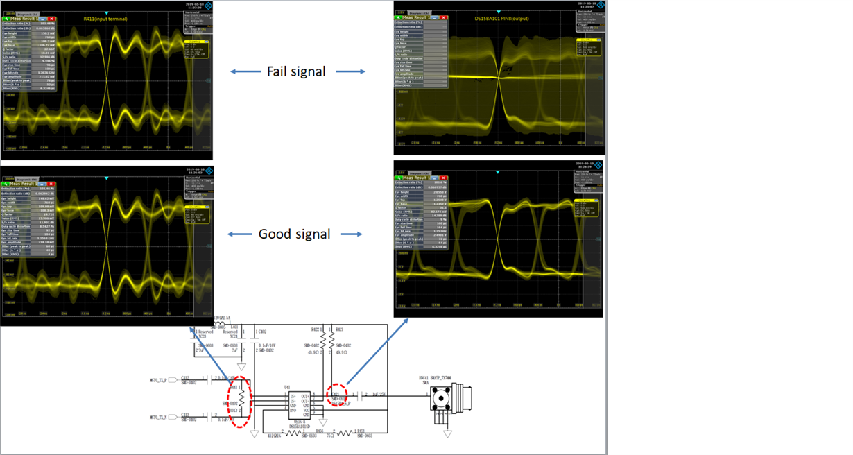
customer provide DS15BA101 input/ output signal 

- Please you kindly help review circuit is OK?

- the DS15BA101 & DS15EA101coupling cap. is 1uF or 0.1uF ?

Have another suggestion.

Thanks!

Steven

  • Hi Steven,
    Looking at the DS15BA101 output when there is a failure, it seems the output gets muted(note there is a line in the middle of the eye diagram). Please ntoe the followings:
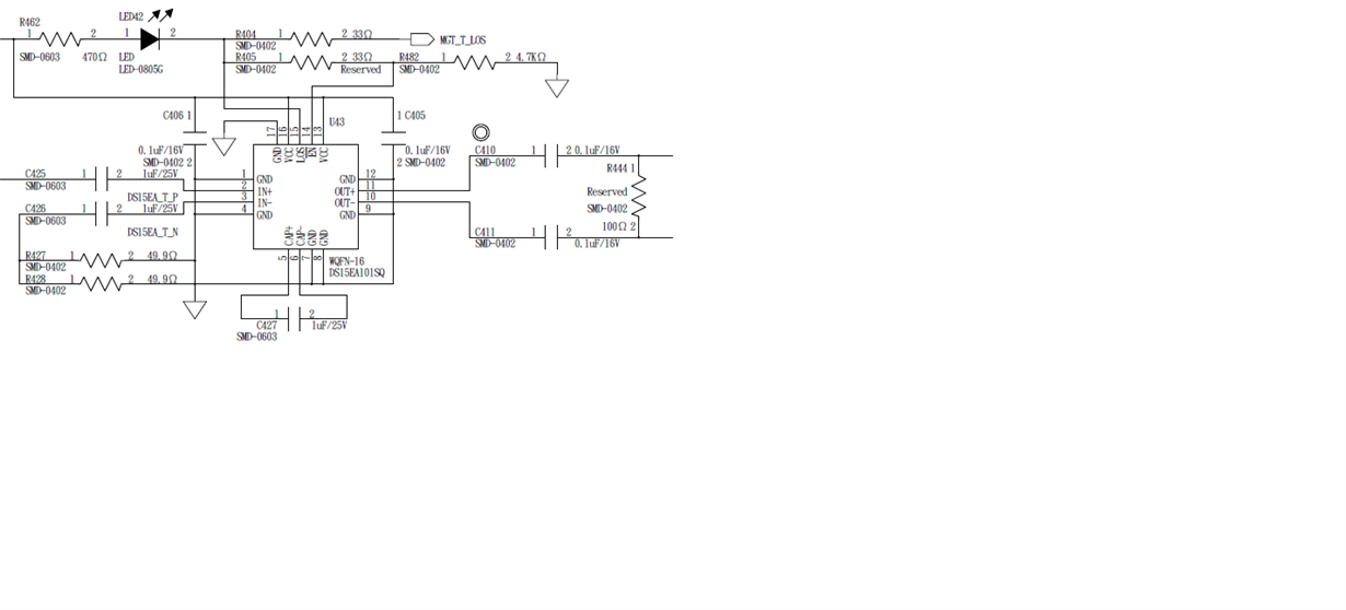
    1). DS15EA101 IN+: I was expecting to see 49.9-ohm resistor to ground on C425 pin 1(please note figure 7 of the DS15BA101 www.ti.com/.../ds15ba101.pdf ). Do you have this in your schematic? With no 50-ohm termination, this could have high reflection which could be negatively affecting DS15BA101 operation.
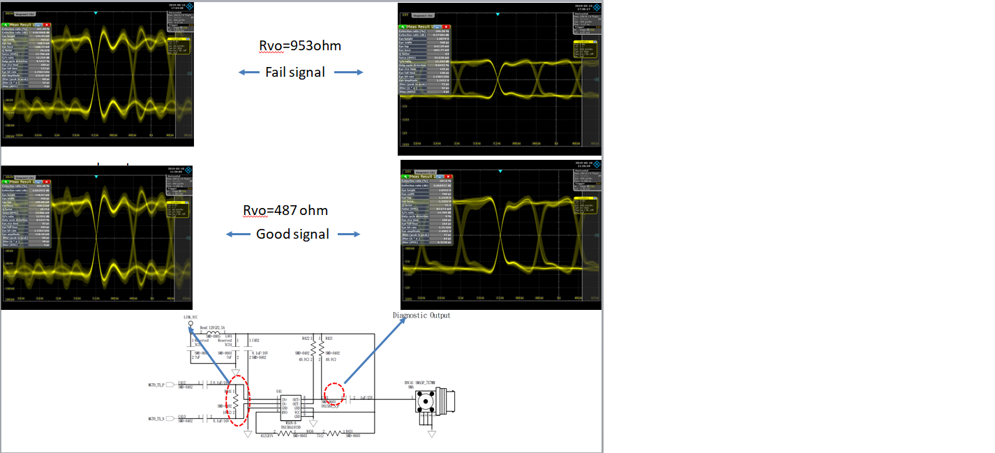
    2). I noted you are using 487-ohm Resistor on pin 4 of the DS15BA101. What happens if you increase this value to something like 953 ohm. Do you see the same problem again?
    Please try check on #1 and #2 as noted above and let me know. Once we take care of #1 or we make sure you have a 50-ohm termination, there is one more thing we can try.
    Regards,,nasser
  • Dear Sir,

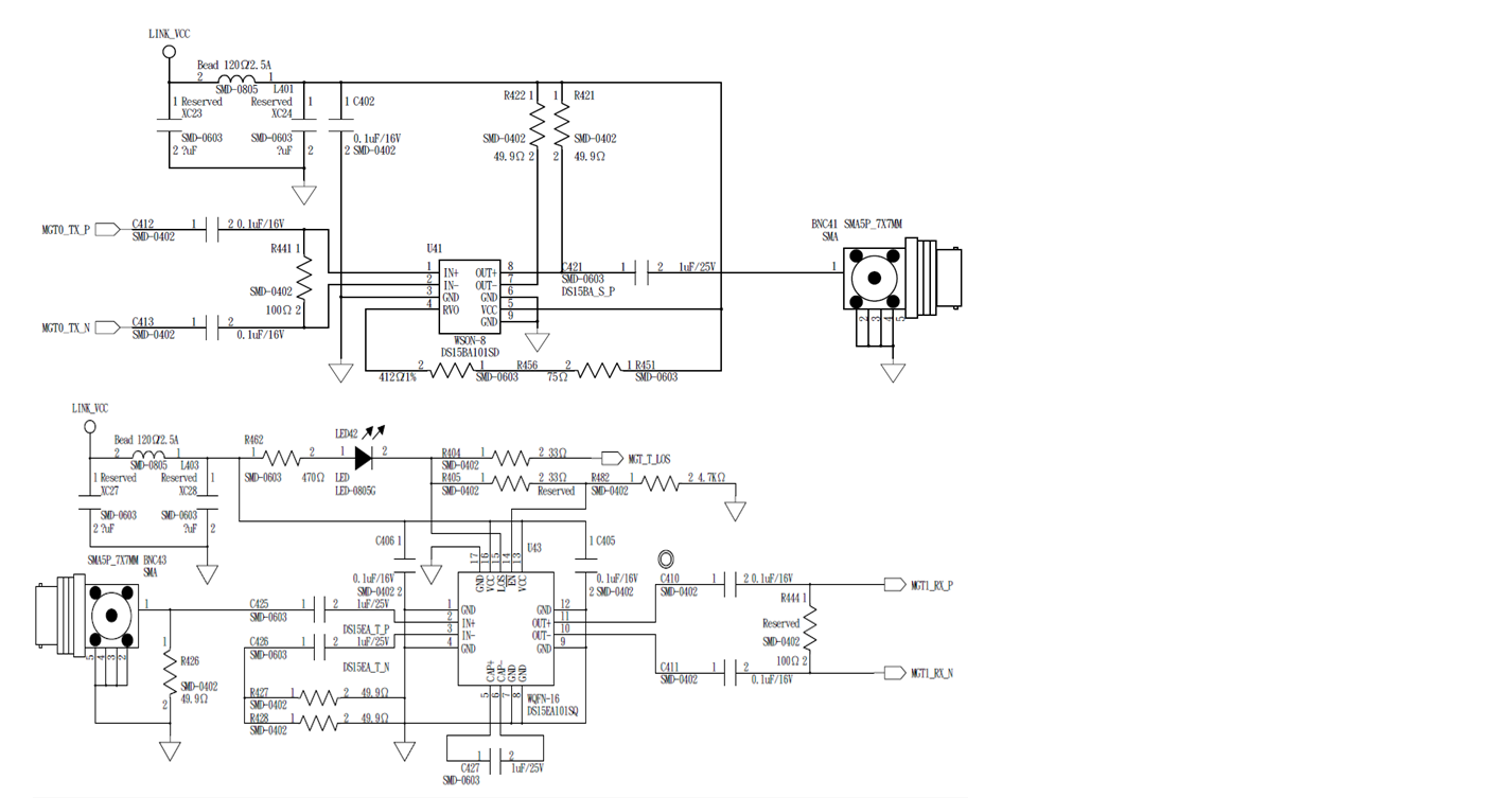
    Please refer below circuit

    #1:  Yes! have put a 49.9ohm(R426) to GND

    #2: I will try Rvo increase to 953ohm test again and update to you result.

    Please you let me know if you have another suggestion.

    Thanks!

    Steven

  • Hi Steven,
    On DS15BA101 OUT- at the moment we only have a 49.9 ohm to VCC. Can you please add another 49.9 ohm to this pin. The other side of this resistor goes to a 1uF capacitor to ground. I am checking if having a balanced impedance on OUT+ and OUT- would make a difference.

    Regards,,nasser
  • Dear Nasser,

    OK! I will try your recommend.

    Rvo increase to 953ohm have improve connect condition but output voltage will reduce..(please refer attached test picture)

    The customer was use RG58/U Coaxial Cable, have any cable length limit ?

    Thanks for your kindly support.

    Steven

  • Hi Steven,

    Changing RVO to 953 ohm will reduces the output voltage swing.

    Please let us know when you run the other experiment and let us know the result. Let's first use 953 ohm for RVO at the beginning.

    Regards,,nasser

  • Dear Sir,

    My customer are use RG-58U 50ohm Coaxial cable, They would know Rvo=953ohm or 487ohm what is length of limit ?

    As above test result, Rvo=953ohm have improve output voltage swing but waveform also reduce, so need they need to reduce cable length.

    Thanks!

    Steven

  • Hi Steven,

    Rvo = 953 ohm and 487 ohm are the limits. We have to choose Rvo within this range. Otherwise, there could be long term reliability if Rvo is less than 487 ohm. This could cause elctro-migration. Also, if you increase this resistor above 953 ohm we may not have an optimum output eye diagram. Please use a resistor value within this range.

    Regards,,nasser