This thread has been locked.

If you have a related question, please click the "Ask a related question" button in the top right corner. The newly created question will be automatically linked to this question.

SN65HVD234: circuit layout

Part Number: SN65HVD234

Hi,

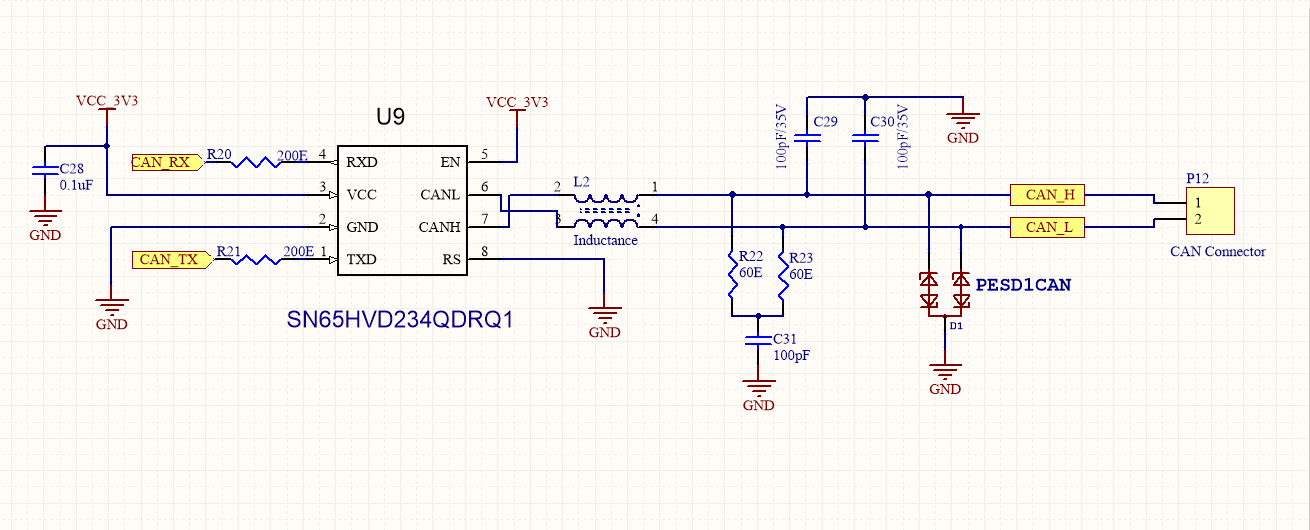
I am currently designing something with this CAN BUS transceiver. And I saw someone post this circuit diagram before, may I kindly ask few questions regarding to this circuit?

1. Is it a must to have R20 & R21

2. What is the use of R22,R23 , C29 ,C30

3. if i am connecting to another can bus transceiver ,  do I need to have the L2 in between ? 

Thanks ,

Regards.

Xuezhi

  • Hi Xuezhi,

    Thanks for coming to E2E with your questions.

    1. No it is not a must have, they just help limit current in case there is a voltage spike on the IO lines.

    2. R22 and R23 are two series 60 ohm resistors, adding up to 120 ohms and serving as the termination resistance on the bus. C29 and C30 are filter capacitors to help with high-frequency noise on the bus lines.

    3. L2 is a common-mode choke is used to help with high frequency current noise, and will help signal conditioning on the CAN bus. It is not necessary to function with another CAN transceiver though.

    Please let me know if you have any other questions.

    Regards,