This thread has been locked.

If you have a related question, please click the "Ask a related question" button in the top right corner. The newly created question will be automatically linked to this question.

SN65HVD234: SN65HVD234DR CANL low resistance to ground.

Part Number: SN65HVD234

Our product is designed with a SN65HVD234DR CAN transceiver. We have found on multiple occasions recently that when doing continuity tests on the harness the product is built into that the CAN Low line has a small resistance to ground (20-40 Ohm) rather than the ~60K Ohm we usually see. We currently have 2 products that use CAN bus. One is the master that connects to a PC (this side is terminated). We then connect 1 or 2 batteries that have a circuit with this CAN bus transceiver. The IC is not powered when it is not connected to the master. We use a certain pulsed load that is detected by the battery to turn on the CAN transceiver and then it proceeds to communicate with the host software through the master and usb interface. There is only termination on the master side as batteries can be multiple configurations. This has never been an issue with previous hardware revisions.

The damage always on the same pin and never on the high side. Is there some protection circuitry or driver that could be damaged on this side but not the other?

The reason this IC was chosen was for its built in transient voltage protection as well as the over voltage protection. We are finding that when our staff does continuity tests on the harness of the battery (which includes power output and CAN lines) that some of them register a very small value on CANL to ground, roughly 20 ohms or so. This would be with the CAN IC powered off. The CAN bus is usually still able to communicate with the master though it can be seen there is no change on the CANL signal with an oscilloscope.


I am wondering what can cause such damage to the IC where the CANL line no longer outputs a signal.

  • Hi Brent,

    A low impedance from CANH or CANL to ground is the most typical failure mode when the device is exposed to an over-stress event (whether it be a transient event such as ESD or a longer-duration event such as a DC short).

    I have a few questions for you, though, in hopes of better understanding how this may be happening:

     - Once a unit shows the low impedance the effect is permanent, correct?  I.e., it is not resolved over time or via power cycle?

     - Does the damage only occur when the device is in the powered-off state?  Or, does it occur during normal operation in which the output driver may be active?

     - Are there any events (such as plugging in a cable, running a particular test, exposure to extreme temperature, etc.) that seem to correlate with the incidence of the failure?

     - Would it be possible to share a schematic showing the CAN implementation?  (If not, could you at least describe what components may be present on the CAN bus lines?)

     - I want to make sure I understand this statement: "...though it can be seen there is no change on the CANL signal with an oscilloscope."  You mean that CANL is at a constant ~0-V level while CANH continues to toggle, correct?  And, is the recessive-state voltage level on CANH reduced to be near 0 V as well?

    Regards,
    Max

  • Brent,

    Typically with damage where there is a low-impedance path to ground, this is evident of some kind of electrical overstress on the pin, which you've alluded to in your post when explaining why you chose this device. Where I've seen it most is with ESD damage from handling or environmental factors.

    Is there any way a block diagram can be shared and schematic? I'm having a little trouble understanding the structure of the application. If you don't feel comfortable posting them on E2E, you can click my username, get my email from the profile page and email me directly.

    When you say there is no change on the CANL signal, is the signal at GND, or is it at the recessive level? And what kind value of termination resistance is used on the master side?

    Regards,

  • I will try to go by your questions in order:

    - The effect to the IC is permanent and once replaced the problem does not persist.

    - The device is tested and calibrated before going into the product. Boards are wired and then conformal coated. PCB's are wired into the product and connected to the master to test operation. So at this point everything works correctly. It is possible the CANL portion may be damaged at this point as I communications is still possible but the signal level for CANL is wrong.

    - No events have pointed to the point of failure as of yet as the failure is only found while doing continuity test once installed in the battery. I am going to request that production tests at least the CAN L to ground resistance at each step through the production cycle and see if I can narrow it down to ESD or another related effect. Of course nothing like this happened in our year of testing for this product.

    - When the board is installed into the battery there is nothing present on either CAN line.

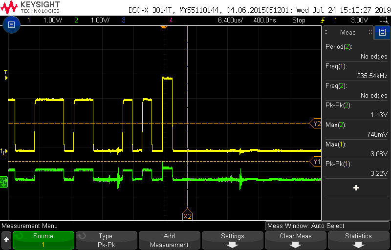
    - As can been seen on the oscilloscope capture it does look like CANL is being pulled in the same direction as CANH rather than the opposite direction. I have seen a couple other failures where the output of CANL doesn't change from 0V though. It also looks like CANH's idle state is 0V rather then ~2V. So both drivers are sitting at a 0V state while not transmitting.

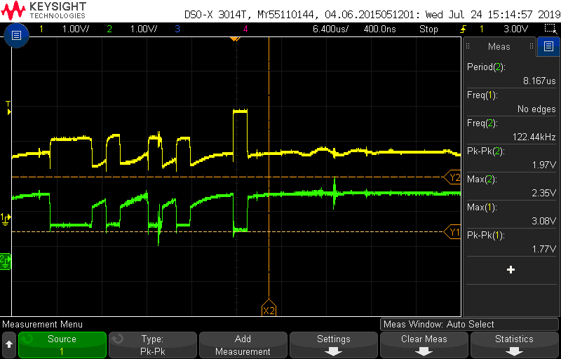
    A good signal shows as the following:

  • Brent,

    That first waveform is what I would expect to see if CANL had a low impedance to ground.  Assuming there isn't something else loading the waveforms externally in this set-up, it looks like the damage has already been introduced by this point.  I think your strategy of checking for damage at various points throughout the assembly/test flow will give the best shot of figuring out the root cause.

    Max

  • Currently checking the CANL resistance to ground at multiple stages of production as it seems to be the only visible sign of failure. Still doesn't explain how so many of an ESD protected device can fail in exactly the same way with little handling done so far.

  • Brent,

    You might try working with your IC supplier to see if they could help perform some failure analysis on one of the units so that we could see what internal structures are damaged (sometimes that gives some clue as to the root cause).  Other than that I'm sure you're already looking into potential differences between the production environment and the testing you had previously done without issue.

    If you haven't already it might be worth probing the CANL line and observing it during different scenarios such as cable insertions (especially if power routed via the same connector) or different power sequences between nodes.

    Max