Because of the Thanksgiving holiday in the U.S., TI E2E™ design support forum responses may be delayed from November 25 through December 2. Thank you for your patience.

This thread has been locked.

If you have a related question, please click the "Ask a related question" button in the top right corner. The newly created question will be automatically linked to this question.

DS90UR124: Lock signal status during non-operation

Part Number: DS90UR124

The DS90UR124 is used for communication, but there are some cases where there is no input signal.

When there is no signal in the input of RIN+ and RIN-, I thought that the output of the LOCK signal is L level, but it seems to be Hi-Z.

There is a description of "Also, the Deserializer LOCK output will remain low until its PLL locks to incoming data and sync-pattern on the RIN± pins." on page 19 of the data sheet.

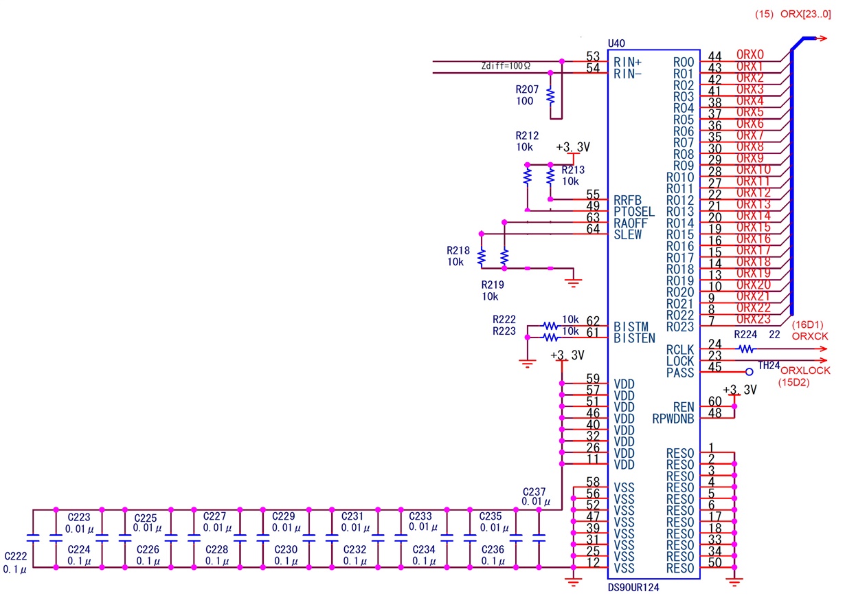
The signal settings are fixed to RPWDNB=H, REN=H, and RAOFF=L.

Table 2 on page 23 of the datasheet shows LOCK=H when PLL is locked, and LOCK=L when not locked.

I thought the lock signal output was L-level, even if there was no signal on the RIN+ and RIN- inputs, just as if the PLL was not locked, but the LOCK output is Hi-Z.

Is it correct that the LOCK output will be Hi-Z when there is no signal in the RIN+ and RIN- inputs when not in power-down mode?

  • Hello,

    When not in power down mode the LOCK pin should not be high-Z. It should be driven either low or high. How have you determined that it is high-Z?

    Thanks,

    Casey 

  • Thank you for your answer.
    There is also a description of "The LOCK output remains active, reflecting the state of the PLL." on page 20 of the data sheet, and I thought that the LOCK signal would not be TRI-state except in power-down mode.
    But as a result of the following checks, I can not longer understand the description of the data sheet.
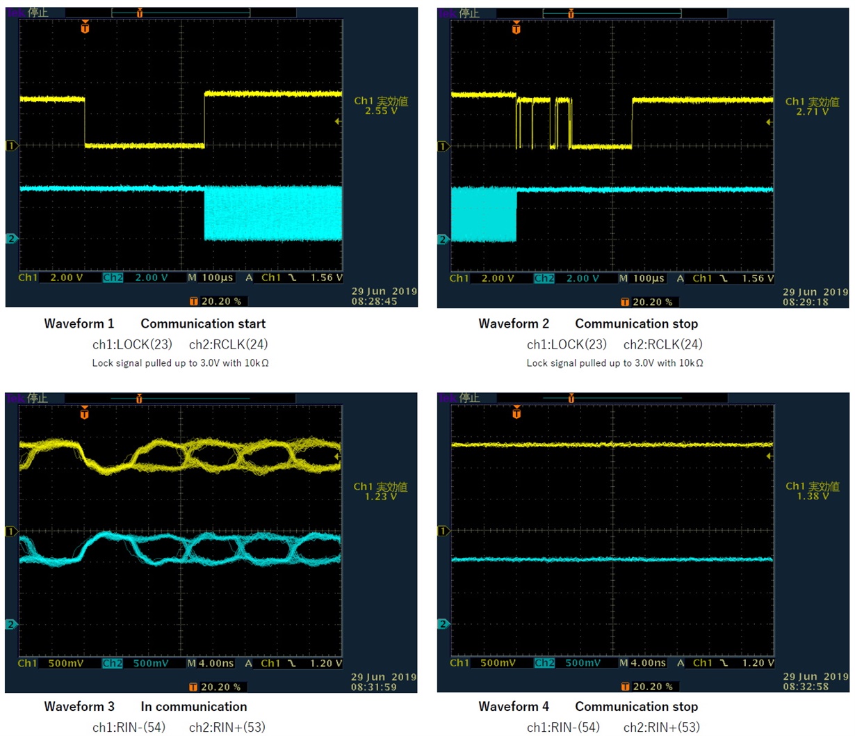
    The lock signal was pulled up to 3.0V (to make it easier to understand, separate from 3.3V) with 10kΩ, and started and stopped communication.
    The waveform of the LOCK signal was 3.0V when communication was stopped.
    If the IC is driving to L, it should be able to drive a load of 10kΩ, so it was determined to be TRI-state.
    Other input signals are level-fixed as described in the schematic pasted to the previous post.
    Paste the retrieved waveform.
  • Hi Hikaru,

    I will try to get an UR124 EVM and test this.

    In the meantime, would you be able to change the 10k pull up resistor to a higher value? May be 100k and 1M.

    The internal pull down on lock pin might not be strong enough to drive 10k.

    Best Regards,

    Charley Cai

  • Hi Charley Cai,
    In the case of 1MΩ and 10MΩ, the LOCK signal was pulled up to 3.0V to measure the start and stop of communication.
    I think it is TRI-state because it is not possible to drive the load of 1MΩ.
    The level of RIN+ and RIN- of waveform 4 posted last time is constant, is this the cause?
    I think that there is such a usage, but is such a state not assumed?
    Best Regards,
    Hikaru
  • Hi Hikaru,

    Sorry for the delay. We just got the EVM for UR124. I will get back to you by the end of this week.

    Best Regards,

    Charley Cai

  • Hi Hikaru,

    Sorry for the delay. I was able to get a hold of the EVM.

    The best method of detecting low vs tristate would be using a curve tracer. 

    I will perform the test and get back to you. 

    Best Regards,

    Charley Cai

  • Hi Hikaru,

    We did a curve tracing on the lock pin.

    When clock signal is removed from TCLK pin on the serializer, the LOCK pin on UR124 will be tristate.

    When clock signal is supplied to TCLK pin and you try to create a unlock condition of disconnecting RIN+ cable, the LOCK pin on UR124 will be LOW.

    Best Regards,

    Charley Cai

  • Hi Charley Cai,
    My understanding is below, is it correct? If it is correct, this resolved my issue.
    When input signals that cannot be locked is input to the RIN+ and RIN-, it is in the UNLOCK state (LOCK=LOW), and when both RIN+ and RIN- input signals are stopped, it is another state (LOCK=tristate) that is not UNLOCK.
    The state in which both RIN+ and RIN- input signals are stopped is not described in the datasheet.
    Best Regards,
    Hikaru
  • Hi Hikaru,

    You understanding is correct. 

    The passage in Resynchronization section is applicable when to when the signal cannot be locked.

    Best Regards,

    Charley Cai