Because of the holidays, TI E2E™ design support forum responses will be delayed from Dec. 25 through Jan. 2. Thank you for your patience.

This thread has been locked.

If you have a related question, please click the "Ask a related question" button in the top right corner. The newly created question will be automatically linked to this question.

TUSB320EVM: TUSB320EVM evaluation board setup issues, GPIO and I2C mode settings

Part Number: TUSB320EVM
Other Parts Discussed in Thread: TUSB320, TUSB320HAI, TUSB320LAI, TUSB321

Dear all,

Currently I'm using the TUSB320EVN evaluation module, and we are planning to use it in our product as a hardware in between the Type-C USB and  our USB-2 Device connection.

I have powered-up the module with the 5.0 Volt barrel connector and there is a constant 5.0 Volt power applyed to module. The R-12 resistor is de-soldered and the switch is set-up  [ 1 0 0 0 0 0 0 1 ] , where 1 = ON and 0 = OFF.

The USB type - C J7 connector is not connected. When I attach the USB J7 connector to my pc, nothing happens, the hardware is not being recognised. There is no any kind of device recognized by my PC.

At this point I have no idea, why it is not recognzed by my pc and what other settings I am missing out.

Thanks in advance

David

  • Hi David,

    What is the state of TypeC_VBUS once the connector is connected? What is your desired configuration so I can better assist?

  • Hello Malik,

    At the moment the evaluation module has only one connection and that is the power, the module is powered over the (barrel connector) through the power supply and the V_Bus aka LP5 has 0.004 voltage level. There is nothing else attached to the eval. module. The switch position as mentioned above is: 100000001 for UFP device mode. The R-12 resitor has been removed as mentioned in application note.

    The OUT1 and OUT2 are having also having GND voltage level. The LP2 (VDD32x) and LP1 (VDD) have voltage levels of 4.40 Volt.

    --------------------------------------------------------------------------- all above without any cable connected to evaluation module ---------------------------------------------------------------------------------------------------------------------------

    David

  • By the way, forgot to mention: the evaluation module gets power from a power supply, on the other end of the kit where the type-c is located, I plug and unplug the type C cable which then is attached to a usb port on my computer.

    The V_bus is 0.4 Volt and no matter I plug the type C connector or not it stays the same level.

  • Hi David,

    Could you also measure the CC1/2 voltages when the PC is connected? The EVM seems to be configured correctly so you should see a voltage greater than 250 mV. this signals that a Type-C connection has been made. Other things to confirm:

    • Measure power directly at VDD320_LP and ensure 3.3V is present.
    • Verify that you have TUSB320LAI or TUSB320. If you ordered TUSB320HAI then PORT_H should be switched to enable the device.
  • Hello Malik,

    So far I have observed the following. When there is no any other power source rather than the USB type -C  plug, during the mating process the Green D10 LED goes on, and at the same time the red LED goes on as well.

    The monitoring of the CC1 and CC2 lines shows following:


    - when plugged : CC1 voltage goes up to  ~ 480mV and stays constant at this level, and CC2 voltage level does not change.

    - when swapped and plugged: the same happens, but for the CC2 line.

    - V_DD320 voltage level is 4.39 Volts.

    ------------------------------------------------------------------------------------

    our device on the evaluation moduel is tusb320 EVM REVB, no other information provided.

    Do you think that it is configured correct in this case=?,

    Any ideas how I could do also checks for current advertisment modes checks on the mentioned evaluation module ?

    David

  • According to datasheet of the TUSB 320, the default current mode in attached state is when the OUT1  is logic high and OUT2 logic low. 
    That being said, as I understand, this mode corresponds to I  =  500 mA current advertisement.

    By the way all this is applied in GPIO mode, that means the I2C is off.

    How can I check the oder 2 modes (medium current, and high current in attached state) as well.

    This would be my question on top the other two question in post above.

    David

  • Hi David,

    You images do not seem to have attached correctly. Could you try to repost them. Your setup seems to be correct. To see other current modes detect in UFP mode you will need a DFP that present advertise that current mode to TUSB320. You could use a signal generator to rise the voltage on the CC1/2 Line to see the other current modes as they are detected (No DFP connected during this test). Only in DFP can you change the advertise current mode and see the attached device consume more or less current.

  •  Hello Malik,

    It seems that, it functions as supposed to the datasheet. So far I was able to spot the following mode state changes on evaluation module.

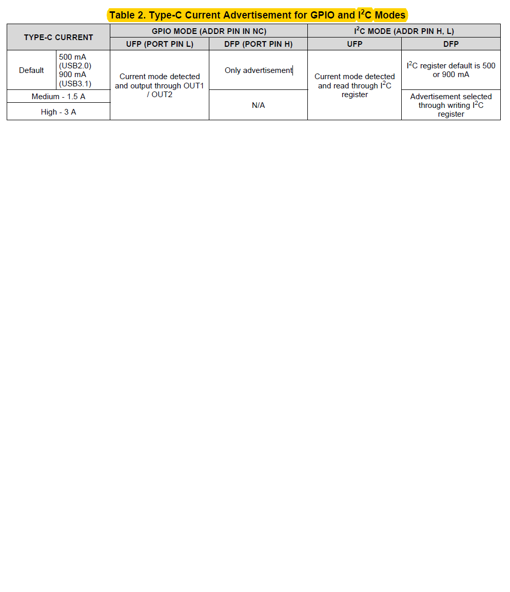
    Lastly there is one thing which is not clear to me, the current advertisement cannot be performed for the DRP mode for the component TUSB320 without I2C mode setup, if I am not mistaken.
    That means, to utilize the 3A current mode within "GPIO" mode setup will be impossible, unless I am using the TUSB 321 component, if I am not mistaken according to the table below.

    Any chance to get hands on the evalaution module from Ti TUSB321?, due to the small size it is impossible to solder in house.


    David

  • Hi David,

    You are correct, TUSB321 should be used in this case. Unfortunately we do not have a EVM for this device. 

  • Hello Malik,

    Could you please tell me what happens it the device attached to USB Type-C with TUSB-320 / 321 driver, tries to draw more current then it is allowed, in any of the operation modes.
    What does TUSB3207321 perform in this situation, when the attached device is attempting to overdrive the allowed / specified limits of current draw.

    Greetings

    David

  • Hi David,

    TUSB320/321 can only advertise or detect the Type-C current mode and relay this a MCU or other processing device via GPIO or I2C. It is up to other power switching/ regulating circuit and MCU or other processing device to detect and prevent a over-current condition based on the Type-C current mode established. TUSB320/321 does not have knowledge of Vbus over-current condition. Vbus_DET only detects the presence of VBUS.