This thread has been locked.

If you have a related question, please click the "Ask a related question" button in the top right corner. The newly created question will be automatically linked to this question.

SN65HVD1791: SN65HVD1291 full duplex transmit signal steadily drifts higher as data is sent

Part Number: SN65HVD1791

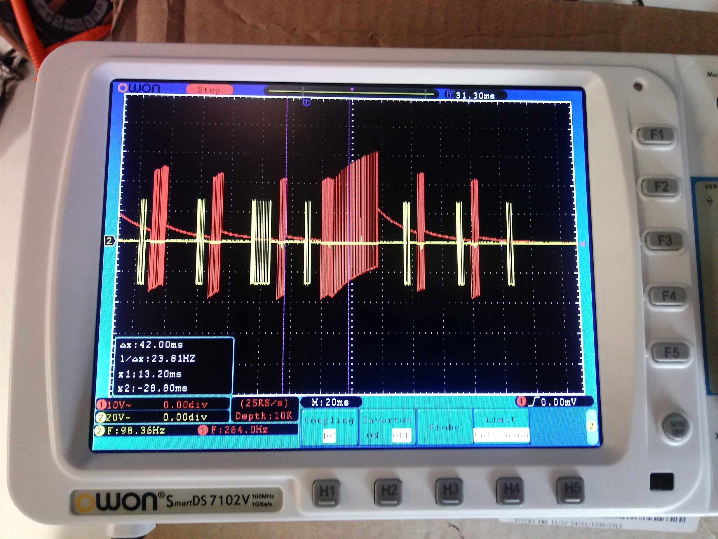
Having an issue with the output of the SN65HVD1791 steadily climbs to a higher reference voltage as pulses are being sent to the slave device. Reference voltage ramps back down to 0V when pulses stop. This is represented by the red signal below. The yellow signal is the recive data from the slave device. I've tried using a pull up resistor (1k) on TX+, and pull down resistor (1k) on TX-. 

  • Hi Will,

    Is the oscilloscope showing the differential signal (VA - VB) or is it showing just one of the differential lines (i.e., VA or VB)?  Where is the reference level for Channel 1.  Is Channel 1 configured for DC coupling?  What is the vertical scale?  (I ask because it looks like the scope is configured for 10 V/div and AC coupling, neither of which would make sense to me.)

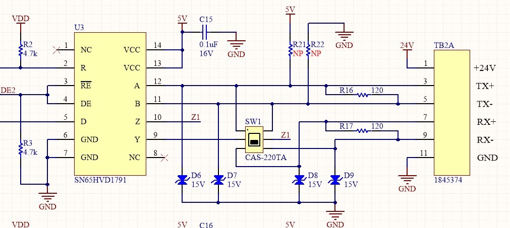
    Could we please review a schematic of your RS-485 implementation so that we can see what external components might be present, how termination is implemented, etc.?

    Regards,
    Max

  • Thanks, Max. I changed ch.1 to DC coupling and the signal no longer ramps. Ch.1 is showing VZ-VY. Ch.2 is VA-VB. Having a field issue where we intermittently lose communication packets from two full duplex slave devices. Thought this irregular ramping of the TX signal was worth investigating.

    Circuit is below. SW1 is there to change the interface from half duplex to full duplex. The slave devices are configured with 110 Ohm termination resistors that can be removed from the circuit with a jumper. Only the furthest slave device has the termination resistor in circuit. 

  • I'm glad there's at least a reasonable explanation for the weird ramping waveforms.  Unfortunately it sounds like that doesn't help you in solving the real issue of lost frames, though.

    The schematic looks fine to me.  (The TX/RX designations on TB2A seem reversed from what I'd expect based on the connection to the transceiver, but I doubt that matters in this case.)

    The pull-up/pull-down resistances you mentioned previously are R21 and R22, correct?  And, did these give no noticeable improvement?

    Is there any sort of operating condition (e.g., temperature/voltage extremes, certain baud rate or time between frames, certain data pattern, loading condition, etc.) that correlates to the issue or is it random?

    Have you been able to catch the issue while observing the differential waveforms on the scope?  The initial waveform you sent doesn't seem problematic besides the AC-coupling issue.  One thing that might be useful is to check the the D/DE/RE/R interfaces as well to see what the MCU/UART devices are seeing.

    Regards,
    Max

  • We haven't tried the pullup/pulldown resistors in the field yet. Just in the lab, where we can't duplicate the problem. 

    We transmit at 38400 baud. We only see lost communication packets when data is actively being sent back and forth between master and slave. No lost packets during times when just handshake signals are being sent back and forth to verify connection. The environment containing the devices are electrically noisy- equipment room of a car wash. When the problem happens, it is only when a large motor that runs a car wash tunnel conveyor chain is on. This motor is about 5 ft from the equipment. RS422 cable between the master and slave devices are only about 6ft between pieces of equipment. Verified cable signal wires and shield are properly terminated. 

    Something else I found- The slave device TX end does not have a termination resistor. Only the slave device RX end has it. The master device (schematic above) has termination resistors on TX and RX lines. 

    I've seen some RS485 full duplex configurations where device 1's TX output is NOT terminated, but device 2's RX input IS terminated. Maxim's MAX13448E functional diagram is shown with this type of configuration. Would this configuration be an issue for the TI SN65HVD1791? 

  • Will,

    No issues only terminating at the RX end.  Dual termination is primarily used for multi-point and bidirectional buses where there may not be a clear starting and ending point for a given message.  If the communication always originates at one end and terminates at the other, though, you can just terminate at the receive end.  This can actually be advantageous since the driver has less of a load to drive and can therefore achieve a higher differential voltage level (which helps both with range and with noise immunity during transmissions).

    Do you have the luxury of observing the relevant signal waveforms when the motor is running?  It sounds like you've got reason to suspect there is noise coupling.  If that can be confirmed it suggests a few different avenues for solutions - for example, filtering circuits (such as additional load capacitances, common mode chokes, ferrite beads, "split" termination), additional biasing resistances to improve noise immunity in the "idle" state, potentially different transceiver devices (with higher output swing or better common mode noise immunity), diving deeper into the shielding/grounding scheme, etc.

    Regards,
    Max

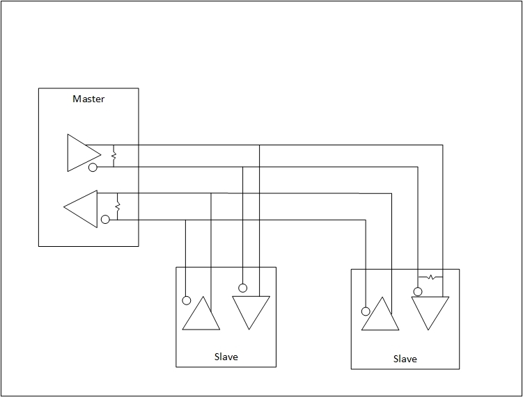
  • I left out some info in a previous post. In this instance, the master device is connected to two slave devices. The diagram is below. I suppose I could turn off, or temporarily disconnect, the first slave device if you think the lack of a termination resistor on the TX output of slave device 2 is an issue. 

    Unfortunately the field site is in a different state, so I can't look at the waveforms unless I'm able to get a trip to the location approved. 

  • Will,

    Thanks for additional info.  In this application the cable length is so short I doubt termination would have much of an impact on signal integrity.  (The delay through 6 ft. of cable would be on the order of 10 ns.  The output transition time from the SN65HVD1791 device is typically 1.7 us.  This means that the transmission media is electrically "short" enough that transmission line effects are not very noticeable - the signal's phase will be similar across the length of the cable at any given point in time.)

    Max