what is the basic issues customer run into when using USB3.0 redriver
This thread has been locked.
If you have a related question, please click the "Ask a related question" button in the top right corner. The newly created question will be automatically linked to this question.
what is the basic issues customer run into when using USB3.0 redriver
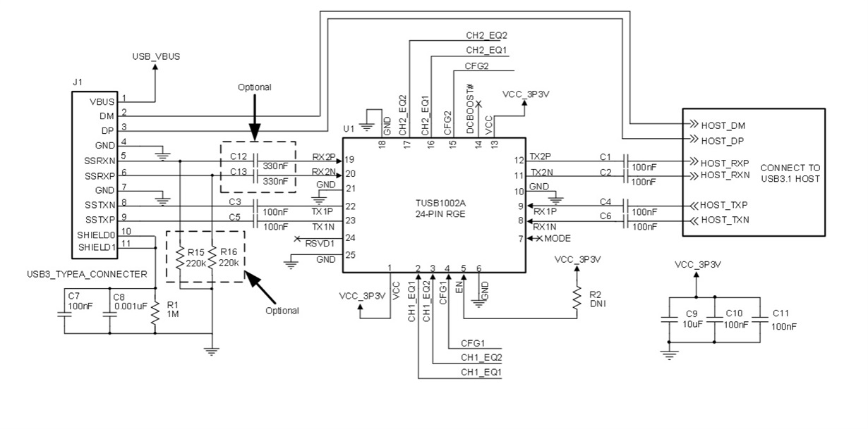
1: Proper AC coupling values when using a USB 3 redriver next to a connector (TUSB1002A as example)
Three implementation options for USB connector to TUSB1002A's RX pins:
1. DC couple TUSB1002A'sRX pins to USB connector.No 330 nF capacitors and no 220 kΩ pull-down resistors.
2. 330 nF capacitors with 220 kΩ resistors as depictedin Figure18. The purpose of 220 kΩ resistors is to discharge the capacitor within 250ms after a USB device is removed from the USB connector.
3. The stub from the 220 kΩ resistor pad may create impedance discontinuities causing negative impact to performance. Assuming leakage current from external components is enough to discharge capacitor,330 nF capacitor without the 220 kΩ resistoris a valid option.
2: Where to place of USB3 redriver.
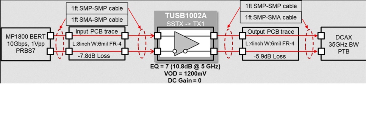
Following HS signal layout guidelines can enable the TUSB1002A to recover a signal from a Host or Device up to a typical 8" FR4 trace. In addition,the FR4 trace from theTUSB1002A to the USB connector can be up to 4". These recommended maximum trace length assumes the Host/Device provides-3 dB of de-emphasis and has a compliant receiver that can recover the 14.5dB loss budgeted by the USB IF for cable+ Host/Device. By adjusting the equalization, de-emphasis and VOD settings of a Host/Device, these maximum trace lengths could possibly be extended.The engineer should work with the Host/Device manufacturer to determine optimal settings.