A related question is a question created from another question. When the related question is created, it will be automatically linked to the original question.
If you have a related question, please click the "Ask a related question" button in the top right corner. The newly created question will be automatically linked to this question.
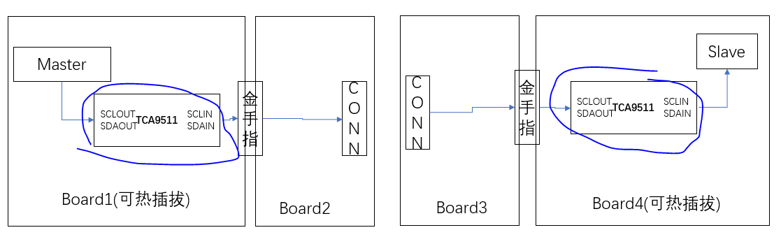
Is Board1 the main I2C bus and Board4 is the hot-swap board? This is a very general overview of your system, so I'm having to make some assumptions.
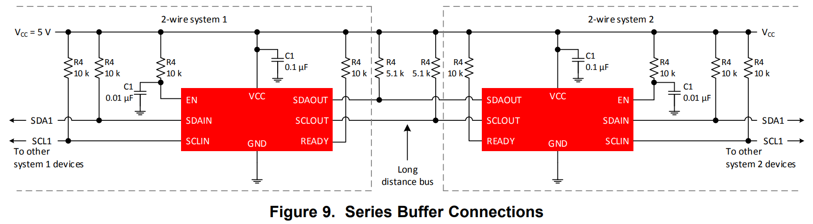
If you're looking to use a series implementation like the one shown below, consider having SCLOUT and SDAOUT face each other respectively for each TCA9511 as shown (flipping what is shown on Board1). This is from section 10.2.1 of the TCA9511 datasheet, which should provide some additional clarity on design requirements.
Yes, Board 1 and Board 4 is the hot-swap board. But our device only have the hotswap function from the Vin side, so must put Vin at hotswap side, am I right?
if that we can't put out side together like the figure you show.
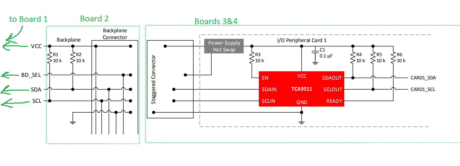
I think I see what you’re saying: you’re saying that Board1 is the main I2C bus (i.e. the “backplane”), and that Board4 is the peripheral hot-swap bus (i.e. the “card”)?
If this is correct, you only need to place the TCA9511A on the card that is being inserted or connected to the live bus. It does not need to be placed on the live backplane bus. Would this drawing somewhat match the application intended?
If this is what you intend, I’d recommend using the TCA9511A only on the hot-swap card.
In the event there is significant need for hot-swap protection on the backplane, you could also consider using an I2C switch. Or if the backplane is already designed and already has the TCA9511A, having them in series should be fine; it’ll just raise the voltage offset a little bit.