Because of the Thanksgiving holiday in the U.S., TI E2E™ design support forum responses may be delayed from November 25 through December 2. Thank you for your patience.

This thread has been locked.

If you have a related question, please click the "Ask a related question" button in the top right corner. The newly created question will be automatically linked to this question.

TCA9554: Bus keeper/holder in SCL PIN

Part Number: TCA9554

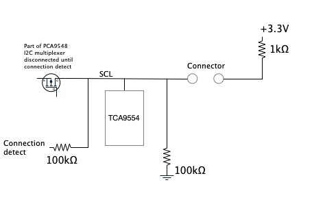
I am looking at an application where we use the SCL to detect connection of the other part of the system.

To do this we have a 100k pull down on the SCL and a 1k pull up in the attached part. So when this is attached the SCL is pulled high and operations can start. The level of the SCL is detected by a different circuit.

I find that when the tca9554 is also on the bus, SCL is low at power on but once the line has been in a high state, the 100k can not pull it down.

The datasheet only states the input current as ±1µA, so this can not account for the problem.

When the tca9554 is removed, the problem is not present and the line can be pulled down.

Changing the 100k to 20k solves the issue for this batch but I need to know what is the resistor value I should use to be certain to pull down the SCL for all tolerances of the tca9554.

  • Hi Sten,

    When you say that the TCA9554 is on the bus, do you mean you have the p-ports connected to the SCL line? If so, there is an internal pull up resistor on the p-ports of about 100k so if what your seeing is a voltage on the SCL line that is about half of Vcc, then this is likely the cause. If the issue is coming from the SCL of our device on the bus, then I'm not quite sure. 

    Would you able to provide a schematic for the TCA9554 for us to review?

    -Bobby

  • I hope this can help

  • Hey Sten,

    Just so I can make sure I'm following this correctly. The SCL is normally held low by the 100k pull down. When a connection is made (in your image when the connectors are shorted) then the SCL is pulled HIGH. 

    What you seem to be seeing is the SCL line is held low even when the connector is shorted to the 1k pull up. 

    Have you checked to see what voltage level the 'low' is? I'm wondering if there is some backbiasing going on from some internal diode to GND (expected low would probably b 0.6V to 1V if this were the case). Our TCA9554 device doesn't have any kind of pull down mechanism on its SCL pin and doesn't back bias, so this shouldn't be the source of the problem. Maybe check to see if the TCA9554 device is properly soldered correctly (no unexpected shorts or device populated 180 degrees backwards). I'd also double check to ensure the schematic and pinout of the TCA9554 device matches the datasheets pinout.

    -Bobby

  • Hi Bobby

    You have the intended function correct.

    What I see is after power on, SCL is low (this is correct). First connection detection works as expected.

    After SCL has been high my problem is that the 100k can not pull SCL down (voltage is ≈1.5V). This points to a bus keeper to hold the line high.

    If I replace the 100k with 20k, it will be pulled down as expected.

    If I remove the tca9554, it also works as expected.

  • Hi Bobby

    My real question is which value of pull down should I use to be certain that it will pull down with all variations in the TCA9554?

  • Hi Sten,

    I don't know what the value of pull down which would work without knowing the root cause. One question I have is the TCA9554 has two sides, the I2C interface side and the p-port side. Is the P-port side of the device connected to the SCL line in your block diagram? If so, then this may explain the 1.5V you are seeing since the p-ports have an internal pull up of about 100k ohms. If the TCA9554 is connected to the SCL on the I2C side then I am not sure what the root cause of the issue is and would not be able to provide a value that would work.

    -Bobby

  • Hi Bobby

    I am ONLY looking at the I2C bus side, specifically SCL.

    SCL is the ONLY connection from the line in question to the TCA9554.

    Sten

  • To expand on this:

    The datasheet expressly states that SCL has only ±1µA leakage.

    This is clearly incorrect, so my question is WHAT is really on that line? My guess is a bus keeper.

    If the datasheet was correct, 100kΩ would easily pull SCL down, but it does not do that. So what is the real deal here?

    Sten

  • Hi Sten,

    I've looked inside of the SCL line in the design file for the device, its only an ESD cell followed by a CMOS gate (a series resistor inside of the ESD cell to prevent inrush current into the gate). The SCL line does NOT have any kind of low level pull down driver like the SDA would have since it adds another concern when PoR goes wrong.

    The only thing I can think of at this point is if there isn't any kind of system error (soldering issues, wrong design, ect) then it may be damage to the device. Have you repopulated a new device onto the 'known bad' board and populated the 'known bad' unit on a new board? (A-B-A test) To see if the problem follows the board or the unit?

    From your block diagram, I'm not sure how the connector makes connection with the SCL line. It may be that when the initial connection is made, a quick transient occurs on the bus and damages our device (I'm assuming an undervoltage condition due to inductive kickback/ringing).

    -Bobby

  • Hi Bobby

    This occurs with all of these boards.

    I will try to find a board that has not yet been used (fresh from production) and apply the high level without kickback.

    There is a TVS on the line just inside of the connector (PDFB050150) with 33pF in parallel and a ferrite bead in series, so protection should be ok.

    In the part where the 1k pull up is located,, we have an EEPROM. This is not damaged.

    br

    Sten

  • Hey Sten,

    Another option we can try is to have you ship me a few known 'bad units' (must be placed in an ESD safe bag) and I can put it on a breakout to see if I see the same behavior. If I do, I can then (unoffically) pass it to a quality engineer who would run a curve trace on it then put it through an ATE to see if we get any fails. If that's something you would like to do, then feel free to shoot me an email at duynguyen@ti.com

    -Bobby