This thread has been locked.

If you have a related question, please click the "Ask a related question" button in the top right corner. The newly created question will be automatically linked to this question.

TPD8S009: TPD8S009

Part Number: TPD8S009

Provide case details or comments: I wish to replace the obsolete CM1233-08DE from ON Semiconductor, datasheet attached, with the TPD8S009DSMR, if you can confirm it is functionally equivalent. I need help with the pin mapping in my schematic. I must have these questions answered in order to use the TPD8S009 in our Abbott Labs production. I've attached the datasheets and a which shows the Cadence blocks I have and how I'm using the CM1233-08E in my schematic. If anyone can help me with this, my email is David.Tipotsch@abbott.com.  I can send you the datasheet for the CM1233-08DE and my Cadence blocks and how I'm using the CM1233-08DE in my schematic presently as well as the TPD8S009DSMR datasheet if you need it to answer my question.  Alternatively, if someone could just clarify for me what the differential line inputs and outputs are for the TPD8S009DSMR, that would be helpful.

Here are my specific questions:

1) Does it take two TPD8S009DSMR to replace one CM1233-08DE (which handles 8 differential pairs)?

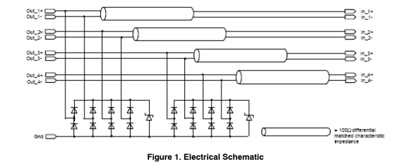
2) What is the mapping of the CM1233-08DE pins OUT_1+, OUT_1-, IN_1+, IN_1-, OUT_2+, OUT_2-, IN_2+, IN_2-, OUT_3+, OUT_3-, IN_3+, IN_3-, OUT_4+, OUT_4-, IN_4+ and IN_4- to TPD8S009DSMR pins? What are the corresponding TPD8S009DSMR pins?

  • Hi David,

    While the TPD8S009 is an 8 channel unidirectional ESD protection device with a 5.5 V Vrwm, it does not seem to be functionally identical to CM1233-08DE. The reason for this is that CM1233-08DE is meant to be connected in series with its protected lines since it has a resistor which seems to be for EMI filtering.

    The TPD8S009 does not have a resistor and should be connected in parallel to the lines it is protecting like so

    You can still use TPD8S009 if you want, but it will not be a P2P replacement. Please let me know if you need any clarification on this or have any more questions.

    Regards,

    Matt Smith 

  • I wish to use the TPD8S009, but I need the 100 ohm characteristic impedance of the CM1233-08E for EMI filtering, which I presently accomplish with a 100 pF capacitor between each differential pair on the input side of the CM1233-08E and the CM1233-08E itself, which includes the impedance. 

    This is my present circuit, the input caps being Johanson Dielectrics 101X14W10MV4T:

    I understand about how the TPD8S009 must be connected differently.  My additional question is, should I place a 100 ohm resistor (I will use a resistor pack) between each differential pair or in series with each line?  Or a 50 ohm resistor on each line?  Or else how do I achieve identical filtering?

    Please sketch an equivalent circuit for one differential pair if possible.

    Thank you

    David Tipotsch

  • Hi David,

    Could you try attaching your schematic again using the insert file or insert media button? Sometimes when you paste it directly in the text box it won't appear.  

    Regards,

    Matt Smith

  • Matt,

    I don't see or have the buttons you are referring to.  Could you please email me at David.Tipotsch@abbott.com and I will email you back my current schematic as well as my proposed understanding of how to use the TPD8S009 to get equivalent functionality.


    Thanks

    David