This thread has been locked.

If you have a related question, please click the "Ask a related question" button in the top right corner. The newly created question will be automatically linked to this question.

TLK105L: TLK105L - TX signal perturbations

Part Number: TLK105L
Other Parts Discussed in Thread: TLK105, AM5728

Hello,

I'm using TLK105L with the following circuitry.

Differential pairs impedance is controlled to 100 ohm.

Length between PHY and Connector is about 2 inches.

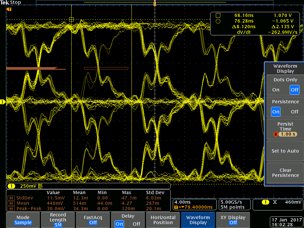
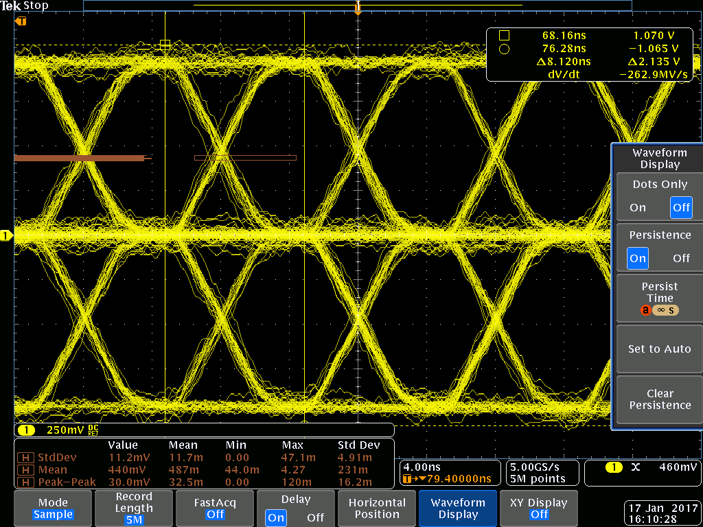
Do you have any idea on possible root causes for these waveform on transmit lines?

TX

RX

  • Hello,

    This might be a signal integrity issue. Can you check the following,

    1. Are the 49.9ohm resistance with 1% tolerance?
    2. Are the 49.9ohm resistors and their respective decoupling capacitors placed close to the PHY?
    3. Can you replace R21 with 0hms?
    4. The center tap of magnetics will need 1uF and 0.1uF decoupling capacitors on both TX and RX pair. Replace C32 with 1uF and 0.1uF for TCT and RCT. PLace new capacitors as close to the magnetics as possible.
    5. Does the magnetics meet the requirements mentioned in Design and Layout guide: www.ti.com/.../slva531a.pdf

    -Regards,
    Aniruddha
  • Hello,

    Our investigations tend to incriminate the high slew rate of TLK105 TX signal. Considering the transmission length is only few inches, we think that the short rising edge is perturbed by reflections.

    We are testing different configurations to slow down the edges by adding serial resistors on the line. I should have result soon.

    Meanwhile, can you tell me if there is other way to improve the signal rising?

    Is there any other PHY that can be use as a replacement?

    Thank you

  • Hello,

    Changing the rise/fall time of the TX signals is not possible through register settings. The components mentioned in the datasheet have been selected after simulations and system validation. Do you still see problems after using the datasheet recommended components?

    We do have a new device for 10/100 applications which can be used in place of TLK105L. It is the DP83822. Since it is a newer design I would encourage you to review it as a replacement for TLK105L.

    -Regards,
    Aniruddha
  • 1. Are the 49.9ohm resistance with 1% tolerance?

    Yes


    2. Are the 49.9ohm resistors and their respective decoupling capacitors placed close to the PHY?

    Yes (1/4'')


    3. Can you replace R21 with 0hms?

    I will test it.


    4. The center tap of magnetics will need 1uF and 0.1uF decoupling capacitors on both TX and RX pair. Replace C32 with 1uF and 0.1uF for TCT and RCT. PLace new capacitors as close to the magnetics as possible.

    I will test it on next respin


    5. Does the magnetics meet the requirements mentioned in Design and Layout guide: www.ti.com/.../slva531a.pdf 

    I will check it

  • Hello,

    Replacing TLK105 by DP83822 improves waveform a lot.

    Now signals seem to be okay between the two PHY but I still have issue for communication.

    Can you confirm that PRU firmware is compatible for both TLK105 and DP83822.

    If not, can you provide new binary or sources?

    Thank you

  • Hi,


    Yes, the drivers should work for both.

    Do you mind sending me the register readout for register 0x0467 and 0x0468?

    What is the value of register 0x17 and 0x0?

    Kind regards,

    Ross

  • Hi,

    Actually, there is a parameter in DP83822 datasheets that is called "Short Cables Threshold", but there is nowhere it is explained how to use this parameter. Could this parameter help if we are using short cables not twisted pairs ?

    On a side note, this is for a transformer-less application (Using capacitors), but the different app notes fount on TI website shows that this should work fine.

    Thanks,
  • Hi Louis-Joseph,

    The 'Short Cables Threshold' is for cable diagnostics and not involved in the link process.

    I am now confused. I thought you were using the AM3xx reference design board.

    Also, you sent us a schematic with a transformer...

    Can you please clarify your setup?

    Kind regards,

    Ross

  • Hello Ross,

    We are using a design based on AM5728 evaluation board (TMDXIDK5728) where we kept three EtherCat interfaces :

    • 2 with transformers
    • 1 without transformer (< 10 inches)

    With TLK105, we observed signal perturbations on the three interfaces. 

    Now, we have changed TLK105 for DP83822 PHY and the three interface eye diagrams seem well.

    Functional testing shows that :

    • communication is okay on both interfaces with transformers
    • communication is not okay on the transformer-less interface

    We are now installing a transformer on the third interface and the communication is OK.

    But it is still not clear what cause the transformer less configuration not to work properly.

    Julien

  • Hi Julien,

    For the transformerless side, do you still have the 50 ohm termination resistors to 3.3V?

    I would like to see the eye diagram for 822 with and without transformer.

    For the diagrams please show TD and RD pairs and let me know if operating in MDI or MDIX.

    Also, are there any special register configuration you are doing?

    Kind regards,

    Ross