This thread has been locked.

If you have a related question, please click the "Ask a related question" button in the top right corner. The newly created question will be automatically linked to this question.

DP83867IS: 10BASE-Te

Part Number: DP83867IS

Hi,

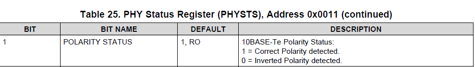
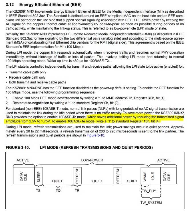
With respect to 10BASE-Te in TI dp83867IS phy chip, I have a few questions.

First, I would like to know if the setting of the sleep mode or wake_on_lan function in the dp83867 affects the receive packet frame.

These functions seem to be disabled by default, but I would like to know if the setting of the above functions affects the operation of 10 BASE-Te and the state change of recive packet.

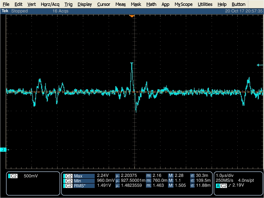
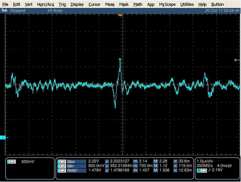
When we compare the voltage difference with the equipment using other phy chip in 10Mbps communication state, we can not find any difference.

1. Equipment used DP83867

2. Equipment used other vendor phy chip

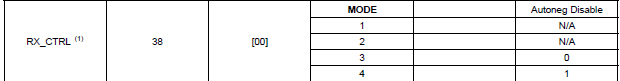
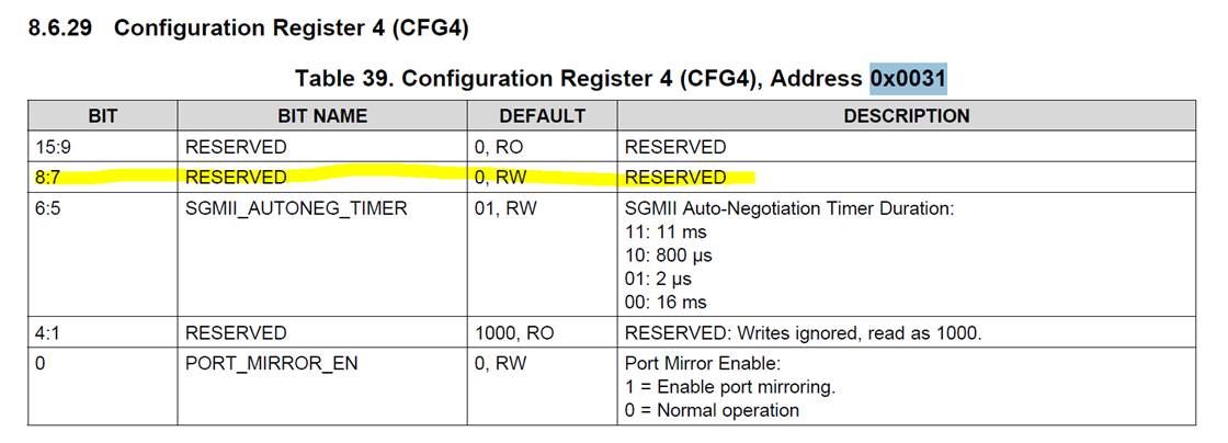
Second, I would like to know if there is a capability to change 10BASE-Te to 10BASE-T in dp83867.

While investigating 10BASE-Te, some other vendor's phy chips support 10BASE-T while changing to 10BASE-Te, so I would like to know if the dp83867 has this function.

(below is from page 33 of http://ww1.microchip.com/downloads/en/DeviceDoc/00002275A.pdf )

thanks,

TS

  • Hello TS,

    Thank you for using the TI forum. Our product expert will get back to you by Wednesday.
  • Hi TS,

    1. In WoL, Phy continue to be active and interrupts the MAC on decoding specific bit pattern, shall not impact the regular data transfer.
    2. In sleep mode, Phy is sleeping and have to be woken-up based on enegy detect. However shall not interfere with regular data transfer.
    3. 10Base-Te to 10Base-T : 10Base-Te is backward compatible and shall work with 10Base-T LP. What's the use-case you are looking where you have to convert a low power driver to high power driver.

    BTW,
    1. Is your design going to be always 10Base-T or 10Base-Te ? or you are switching between 1G/100M/10M ?
    2. From your mail, looks like you main concern is do a low power design. How much is the power budget you have on the design.


    Regards,
    Geet
  • Hi Geet,

    thanks for your answer.

    This is reply to your inquiries.

    1. What's the use-case you are looking where you have to convert a low power driver to high power driver.

    -> Currently, we have 10BASE-T standard for all devices that are connected with TI DP83867IS with 10M and do not have good rx.

    This is to test whether 10M communication is not possible due to this standard difference.

    2. Is your design going to be always 10Base-T or 10Base-Te ? or you are switching between 1G/100M/10M ?

    -> It is designed to use 1G / 100M / 10M using auto negotiation.

    3. From your mail, looks like you main concern is do a low power design. How much is the power budget you have on the design.

    -> I do not know the details of the power consumption of the HW part of the SW side, but I changed the phy chip to the TI DP83867IS in the originally manufactured equipment, so the power consumption will not be shortened.

    thanks,

    TS

  • Hi TS,

    10BaseT and 10BaseTe shall be backward compatible. Just to double confirm, I tried a test in lab by linking DP83867 with 10Base-T and data transfer as well.

    Regards,
    Geet
  • Hi Geet,
    Can we change the setting from 10BASE-Te to 10BASE-T in the DP83867IS phy chip that we asked?
    If it is possible, I have not answered the method yet.
    Please let us know.
    thanks,
    TS
  • I need just one thing.
    - Which register of DP83867IS should I change for disable EEE?
  • Hi TS,

    - DP83867 supports only 10Base-Te and driver can not be configured for 10Base-T

    - For disabling EEE, please refer to below post.

    e2e.ti.com/.../2036811

    Regards,
    Geet
  • Hi Geet,

    Thank you for your quick response.

    The EEE disable you told us did not work out.

    Below is our additional questions.

    1. 0x31 bit7 is not defined on the datasheet.

    Q1> It looks like a register that TI does not open, but can I get public documents?

    2. 10Base-T seems to have the ability to reverse the cable polarity to auto.

    We found the register to look up status information in the datasheet.

    Q2> Please provide a register to enable / disable this function.

    thanks,

    TS

  • Hi TS,

    When you configure register 0x31h, are you using the extended register access method outlined in the SMI section?
    Register 0x31h cannot be accessed through direct register access.
    Additionally, you can use the RX_CTRL pin to hardware configure the PHY for disabling the operation. Please set the strap to MODE 3.

    For 10BASE-Te, polarity detection is done automatically and cannot be disabled. When the PHY is powered-on, it is looking for both the correct and inverted polarity. We are not purposefully inverting the polarity on our transmitter. This polarity status is what we detect from the link partner.

    Kind regards,
    Ross
  • Hi Ross,

    To access Register 0x31 is done in the way described in TI DP83867 datasheet (snls504b.pdf) document on page 27, "8.4.2.1 Extended Address Space Access" (exactly 8.4.2.1.3 and 8.4.2.1.4).

    Registers with addresses after 0x1f are known to approach this.
    Are you saying this way?

    On the datasheet, bit7 of the description of 0x31 register is reserved, so I asked.

    thanks,

    TS

  • Hi TS,

    The bit is reserved because we prefer the PHY to boot in the mode without having to disable the advertisement.
    A suggestion for register access is more of a mitigation if bootstraps cannot be changed.
    Can you change the bootstrap for MODE 3 operation?

    Kind regards,
    Ross
  • Hi Ross,

    The 10M issue is not resolved yet.

    I would like to remind you once more about the phenomenon.

    When linking to 10M, TX is normal but RX is not recognized as normal frame by CPU.

    (Rx non-octet aligned frame)

    And the answers to the questions below are not coming in properly ...

    (Question) Like '0x31 bit7', it is not listed in the datasheet, but is there a Register with a hidden function?

    In response to the above, you asked me to change RX_Ctrl to mode3, but I do not know why.

    This is a completely different answer to our question.

    And the corresponding register bit is for EEE function enable / disable and I do not know how it relates to RX_Ctrl boot starp (Auto nego).
    RX_CTRL setting does not determine 10M support with Auto Nego enable / disable register.

    [Additional question]

    The response to the CPU (P1011 @ NXP) Agent connected to PHY is that SGMII detects non-octet frame and returns error.

    And we got the answer to remove nonstandard SGMII signaling extensions.

    Find out if there is a different extension signal from the standard specified in the Cisco SGMII Specification.

    (NXP  answer)

    I assume you read the 0x0c10 code from the RxBD status word. Error 0x10 is
    NO, non-octet aligned frame. Description can be found in T1020RM, Section 15.9.8.3. This error basically means that the PHY irreliably detects or incorrectly reports the end of the frame. It may happen either due to unsupported PHY/MAC protocol extensions or due to conditions on the line. The suggestion is to suppress all SGMII signaling extensions not specified in CISCO SGMII specification 1.7,   diagnose the PHY and the link to the far end.

    Also, bit [7] of configuration register 4 (0x0031) is cleared if RX_CTRL is not set to Mode 3 or 4 on the datasheet. As mentioned earlier, the corresponding register description is not in the datasheet.

    And when turn on / off EEE need to set the corresponding bit.

    <For disabling EEE through software, write ‘0’ to bit 7 in register 0x31>

    Please also let us know the substance of the Register.

    thanks,

    TS

  • Hi Ross,

    Thank you for supporting TS, today I had a meeting with customer and he wants to get below questions. Customer got some answers from you already, but it has a little bit confuse still. Alright to make sure,


    1. Does DP83867IS support 10base-T officially?
    2. TS got the answer to disable the E of TE, 0x31 bit 7 should be cleared. TS followed that way, but no improvement. and after then TS got again "RX_CTRL mode3 setting". However, this is no relationship between "EEE disable" and "Auto nego on/off". Is there another method to disable "EEE"?
    3. Is there any hidden register to disable for "EEE"?
    4. some phy vendor like Realtek is well connected with T mode. However, phy devices of VSC8221 / AC201 / BCM56150 internal connection is not available. If DP83867IS supports T-mode, can you please test with VSC8221 / AC201 / BCM56150 internal PHY (if it is possbile)(these are ok with 10M Link and 10M traffic TX. HOWEVER, 10M TRAFFIC RX IS NOT AVAILABLE) and let me know the connection result.
    (if test is not available, please let me know, I can ship it to you)

    Thank you a lot in advance.

    Regards.
  • Hello Max,

    Please find my replies below,

    1. This question has been previously answered in this thread. DP83867IS supports only 10Base-Te, however 10Base-Te is backward compatible with 10Base-T. This has been validated in the lab and we were able to successfully transfer packets to 10Base-T link partners.

    2. Bit 7 of register 0x31 is related to RX_CTRL strap. In correct strapping can cause link stability problems. From the description it looks like customer is facing problems with data transfer and not link stability. This will need further debug but please continue to clear Bit 7 of register 0x31. If this cannot be done, then modify the strap resistor value on the system to put RX_CTRL in mode 3.

    3. The comment about clearing bit 7 of register 0x31 is now added to the datasheet. Customer do not have to edit any other register to disable EEE.

    4. DP83867IS has been tested with 10Base-T link partner but not the specific ones that you have mentioned in the comment.

    Further Debug Steps,

    1. Confirm that SGMII autoneg is enabled by reading bit 7 of register 0x14.

    2. Confirm that link is up and stable by reading bit 10 in register 0x11 multiple times.

    3. Confirm that bit 7 of register 0x16F is cleared to '0'. This is needed for 10M SGMII operation. If this bit is not cleared then write '0' to it and send a soft restart command by writing 0x4000 to register 0x1F. Try sending and receiving packets after 10M link up.

    4. If point 3 does not help resolve, check bit 0 of register 0x37 to verify that SGMII auto-neg is complete. If SGMII auto-neg is not completed, then try increasing the SGMII auto-neg timer by writing 0b00 to bits 6:5 of register 0x31. Send a soft restart command by writing 0x4000 to register 0x1F. Trying sending and receiving packets after 10M link is up.

    Let me know the results from the debug steps.

    -Regards,

    Aniruddha

  • Hi Aniruddha,

    We will proceed with your debug step and will share the results soon.

    By the way, I want to mention two things below.

    1. The phenomenon is that the CPU does not recognize the RX from the DP83867 as a normal frame.

    (The response to the CPU (P1011 @ NXP) Agent connected to PHY is that SGMII detects non-octet frame and returns error.)

    So please find out if there is a different extension signal from the standard specified in the Cisco SGMII Specification.

    2. If RX_CTRL is set to mode 3, auto neg of SGMII is disabled and communication is not possible.

    thanks,

    TS

  • Hello TS,

    I will look in to the 1st point you mentioned more closely. However in regards to your point 2, RX_CTRL strap in mode three does not disable auto-neg. Mode 3 will configure 'Autoneg Disable' to '0' which means that auto-neg is actually enabled. Are you seeing the auto-neg getting disabled when you try to strap RX_CTRL to mode 3?

    -Regards,
    Aniruddha
  • Hello Aniruddha,

    We've already tried the "Further Debug Steps" that you recommended, and have tried again but can not improve it.

    1. Confirm that SGMII autoneg is enabled by reading bit 7 of register 0x14.

    -> It is enabled.

    2. Confirm that link is up and stable by reading bit 10 in register 0x11 multiple times.

    -> Link status is kept up.

    3. Confirm that bit 7 of register 0x16F is cleared to '0'. This is needed for 10M SGMII operation. If this bit is not cleared then write '0' to it and send a soft restart command by writing 0x4000 to register 0x1F. Try sending and receiving packets after 10M link up.

    -> Bit7 is kept at 0.

    4. If point 3 does not help resolve, check bit 0 of register 0x37 to verify that SGMII auto-neg is complete. If SGMII auto-neg is not completed, then try increasing the SGMII auto-neg timer by writing 0b00 to bits 6:5 of register 0x31. Send a soft restart command by writing 0x4000 to register 0x1F. Trying sending and receiving packets after 10M link is up.

    -> Do not need to increase the timer because auto-neg is done. I tried Soft restart but it does not improve.

    It seems that TI needs to check with the problematic Link partner PHY product.

    thanks,

    TS

  • 1. Initially set to mode4, even Link at 10M was uneasy,
    2. set Mode3 and check link is OK and autoneg enable.
    3. At 10M, RX packets are broken with some link partners.