This thread has been locked.

If you have a related question, please click the "Ask a related question" button in the top right corner. The newly created question will be automatically linked to this question.

DP83640 PHY interoperability issue with Micrel Ethernet Switch KSZ8895MQ when AC coupled

Other Parts Discussed in Thread: DP83640

AC coupled link between DP83640 PHY does not work with Micrel Ethernet Switch which has internal bias and termination.

When transformerless connection, using 0.1uF/0603/X7R capacitors and 50 Ohms termination resistors to 3.3V on PHY side is used, link is established and stable at 100Mb/FD, PHY receive pair operates fine, but in transmit direction no packets are received by a link partner.


Apparently Micrel Ethernet Switch does not receive 2-level (single ended) pattern coming from DP83640, no packets are received, while link is established and steady at 100Mb/FD or HD. Differential signal looks OK, but single ended waveform does not look like MLT-3.


When link speed is set to 10Mb, ot through magnetics, link operates fine in both directions.


When output signal from DP83640 is attenuated (using 18Ohms termination instead of 50Ohms) link starts to operate at 100Mb, but not on all boards, on some boards with DP83640 link starts dropping, becomes unstable

Same Micrel Switch works fine in both directions when other (non-TI) PHY is used, AC coupled same way, but in that case MLT-3 waveform from/to PHY is both single ended and differential.

  • Could you provide a schematic of the design for review?  If you would prefer not to post it on the forum, let me know and I will provide an email address.

    Do you have register access for the DP83640?  It may be helpful to confirm the configuration.

    You mention that the differential signals look OK.  Could you share scope shots?

    Thanks,

    Patrick

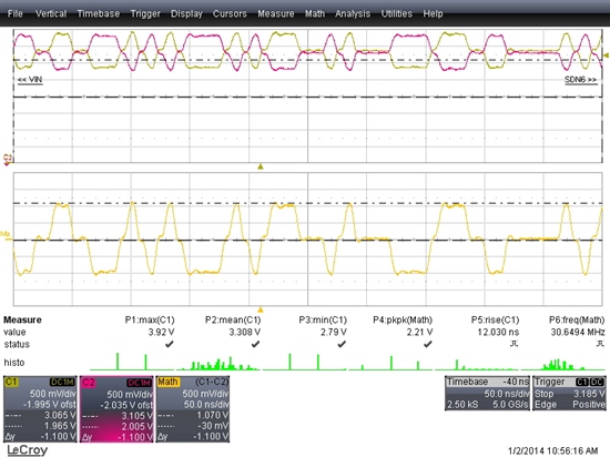
  • This is the waveform at PHY side, before AC coupling capacitors:

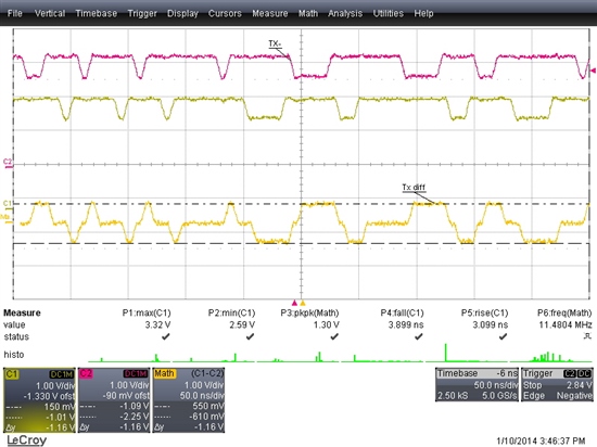
    Same signal pair on Switch side, some offset present:

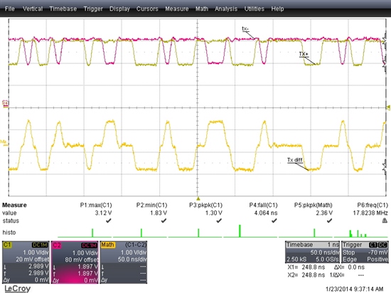
    When termination resistors are replaced with 18Ohms, amplitude is lower and switch receives and forwards packets. I used better probe grounding, so signal looks better on this scope shot, but in fact it is not.

  • Registers    
    Hex  DP83640 Value
    0 Basic Mode control 3100
    1 Basic Mode status 78ed
    2   2000
    3   5ce1
    4 Auto-neg advertisment 01e1
    5 Auto neg link partner 45E1
    6 Auto neg exp reg 0007
    7 Auto neg Next page Tx 2801
    8   0000
    9   0000
    10 PHY status 0615
    11   0000
    12 memory int 0000 (2C00)
    13 pagesel 0000
    14 False Carrier Sense Counter 0000 (0002)
    15 Receiver Error Counter Register 0000
    16 100 Mb/s PCS Configuration and Status 0100
    17 rmii and bypass 0001
    18   0000
    19 PHY Control  8021

    Per PHY registers, link is established and stable, at 100Mb/FD. Ethernet Switch reports the same link state. PHY receives packets, but no packets are received by the Switch from the PHY, although being sent every second.

    In previous post, first figure shows properly operating Rx signal at the PHY, coming from Ethernet switch, which looks like MLT-3 pattern both single ended and differential.
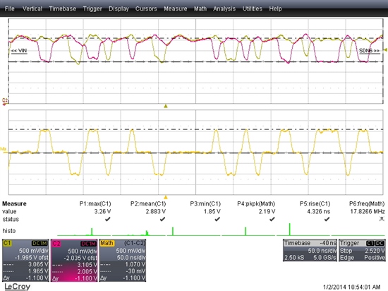
    DP83640 PHY Tx signal,which is not received by the switch,  measured at the output pins of PHY, is shown below:

  • Part of  schematic with PHY connection shown below:

    Signals are directly connected to switch (just through the connector) since Switch has internal bias and termination.

    Note: Other port on the Ethernet switch, connected using AC coupling to non-TI PHY operates correctly at any speed.

  • I do not see any problems with the portion of the schematic being shown.  I will discuss this with my colleagues and see what recommendations we can make.

    Patrick

  • Hi Patrick,

    Any ideas from your colleagues?

    Link works OK at 100Mb when signal is attenuated by roughly 50-60%, either by changing termination (pull-up to 3.3V) from 50Ohms to 18Ohms at PHY, (but does not work when R>25Ohms) or when Vref resistor is changed from recommended 4.87k to 8.25k (but link drops when Vref resistor is inreased over 9.1k ).

    None of these is acceptable fix, since neither works reliably over a batch of boards, but may provide a tip how to resolve this issue.

    Regards,

    Predrag

    .

  • I agree with your thinking that changes to the terminations or the Vref resistor are not acceptable as a fix.  We need to dig a bit more to understand the underlying issue.

    What is used as the X1 reference clock source for the DP83640?

    What is the source of the packets when the DP83640 is transmitting?

    Patrick

  • Reference clock is coming from Abracon ASEM1 LVTTL oscillator, 25.0000MHz, 50ppm. Pin X2 is left open.

    Source of the packets is Hercules RM48L952ZWT, MII interface.

    Link works error free when connected through magnetics, or when running at 10Mb, so I do not suspect an issue on MII side. No packets received by a link partner when at 100Mb and AC coupled.

    I still need to see how the output stage of the PHY TX+/- looks like, any spec - current, voltage, impedance, diagram - would help.

    Regards,

    Predrag