This thread has been locked.

If you have a related question, please click the "Ask a related question" button in the top right corner. The newly created question will be automatically linked to this question.

DS80PCI102 and AC coupling capacitors locations

Other Parts Discussed in Thread: DS80PCI102

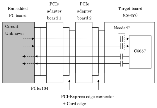
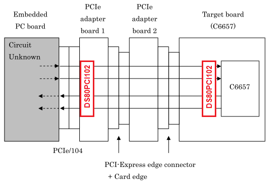
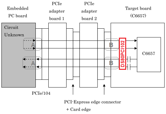
For Typical Application, DS80PCI102 datasheet describes that a pair of AC coupling capacitor is placed on both a transmitter side and a receiver side.

Board Design Guidelines for PCI Express Architecture describes the AC coupling as follows.
 
"Cap location:
 - Along Tx pairs on system board
 - Along Tx pairs on add-in card"
 
Board Design Guidelines for PCI Express Architecture
http://www.pcisig.com/developers/main/training_materials/get_document?doc_id=6d37ec2f8543fc1f9d8ace6264d08b469f57e5f1
AC Coupling Caps (Page 15)

For general PCI Express application, a pair of AC coupling capacitor should be needed on only a transmitter side.

What are the situations that it is needed on both a transmitter side and a receiver side?

Best regards,
 
Daisuke


  • Hi Daisuke-san,

    You are correct. Only one pair of AC coupling caps is required, and you can remove the redundant capacitor.

    While having two AC coupling caps is technically possible for signal transmission, there is not much benefit to having two AC coupling caps in series, due to an increase in vias and discontinuities in the signal path. One pair of AC coupling caps is enough.

    Thanks,

    Michael

  • Hi Michael-san,

    Thank you for your reply.

    Why is there two pair of AC coupling caps in Typical Application in DS80PCI102 datasheet? Is the reason related to using the Interconnect Cable?

    For C6657 DSP in the C6657EVM, there are the AC coupling caps on both the transmitter side and the receiver side. The PCIe serdes lines connect to the AMC connector.

    https://www.einfochips.com/index.php/partnerships/texas-instruments/tms320c6657-evm.html#5-resources

    Best regards,
     
    Daisuke


  • Hi,

    Please give me an answer as soon as possible. Your prompt reply would be appreciated.

    Best regards,

    Daisuke


  • Hi Daisuke-san,

    Thank you for your patience. 

    There is a mistake in this datasheet diagram as it relates to the application. In an active cable (with one DS80PCI102 on each end), the designer will have free choice over the components on either end of the interconnect cable. In this case, only one pair of AC coupling caps are necessary between the two ICs. While including a second pair of AC coupling caps does not necessarily damage the overall system beyond functionality, the second pair of AC coupling caps will contribute to signal integrity degradation, such as lower overall series capacitance and increased signal loss through vias due to routing, since capacitors must be on the top layer and signals could be traveling on middle board layers.

    It is important to note, however, that there are situations where there are two pairs of AC coupling caps. In a situation where you are only able to control one side of the design (for example, if you are making a motherboard where any vendor's add-in card may be placed in the slot), it is typical  to have an AC coupling cap on transmit and receive side in case the add-in card vendor does not provide one in the signal path on their board. In this case, situations with two pairs of AC coupling caps are a possibility when both parties place AC coupling caps on their transmit and receive side for insurance against unwanted DC coupling.

    Thanks,

    Michael

  • Hi Michael-san,
     
    Thank you for your reply.

    In the case of our customer, the board designed by them is connected to the PC board purchased by them. Only one pair of AC coupling caps will be placed on the transmitter side on their board. I will suggest that they check whether there are the AC coupling caps on the PC board.

    I have a new question for the PCIe connection of their boards. The target board is connected to the PC board via two adapter boards and three connecters. The connection is shown as follows:

    There is no PCIe repeater on two adapter boards. Is the repeater needed on each adapter board?

    Best regards,
     
    Daisuke


  • Hi Daisuke-san,

    This depends on the amount of trace and interconnect loss that is expected through the adapter boards and interconnects. If the configuration above will never change and the total loss from PC board TX/RX to target board RX/TX will always be <10-15 dB, the system may be able to negotiate a good signal between TX and RX without the repeater.

    However, in the situation where overall loss will be significantly more than 15 dB, the PC board and target board may not be able to negotiate a good link with high signal integrity. My instinct is that only one repeater is necessary, and it should be placed near the RX side with less post processing capability. However, it is more suitable to make sure I understand the system parameters. Do you know the approximate amount of board trace or approximate loss per board in each situation? This will help us determine if it is better to have one or two repeaters.

    Thanks,

    Michael

  • Hi Michael-san,

    Thank you for your reply.

    Our customer can show only the scattering parameters for between the connecters on the adapter boards. Can this help to determine if it is better to have one or two repeaters?

    Best regards,

    Daisuke


  • Hi Daisuke-san,

    Yes! If your  customer has a Touchstone .s4p file with the scattering parameters that they can share, it will help us understand what kind of losses to expect from one end of the adapter to another. Please ensure that the scattering parameters are inclusive of frequencies up to at least the Nyquist frequency. For example, assuming they are running PCIe Gen 3 (8Gbps) with the DS80PCI102, the scattering parameters of most interest to us are the insertion loss measured at 4 GHz.

    Thanks,

    Michael

  • Hi Michael-san,

    Thank you for your reply.

    Our customer's PCIe system needs one lane with Gen 2 (5Gbps). I attach the s4p file and image including the scattering parameters between the connecters via two adapter boards. Please keep in mind that the parameters do not include concerning the PC board and the target board.

    4135.CH1_TX_THRU_0.S4P.txt

    Best regards,

    Daisuke


  • Hi Daisuke-san,

    I was able to model the loss based on the .S4P file you sent over on my end. I am assuming that the loss from connector to ASIC on both the PC board and target board is negligible (< 5dB). Therefore, if my understanding is correct about where these S-parameters are measured (from PC board to target board) and your customer is designing for PCIe Gen-2, then you should only need one repeater in the signal path. 

    Below is the Gen-2 SDD21 Insertion Loss taken at 2.5 GHz:

    The DS80PCI102 provides up to 36 dB of EQ gain and 12 dB of De-emphasis, so I do not see a need for two of them. Having one repeater in the signal path will act to improve signal margin and eye diagram observed.

    If your customer chooses to utilize Gen-3 instead (@ 8G), it will still work with one repeater, as the loss only increases from ~6.7dB to ~9.1dB.

    Thanks,

    Michael

  • Hi Michael-san,
     
    Thank you for your reply.

    Please tell me where the DS80PCI102 should be placed. If the PCIe device (C6657) on the target board has the RX side with less post processing capability, should only one DS80PCI102 be placed near the C6657? If the PCIe device on the PC board has it, should only one DS80PCI102 be placed near end of the PC board side on the adapter board? If it is unknown, should the DS80PCI102 be placed on the both boards?

    Best regards,
     
    Daisuke


  • Hi Michael-san,

    Sorry, I was confused.

    Please tell me where the DS80PCI102 should be placed for each differential pair on one lane.

    You said that only one repeater should be placed near the RX side with less post processing capability.

    Should one DS80PCI102 be placed near the PCIe device (C6657) on the target board? Should another DS80PCI102 be placed near end of the PC board side on the adapter board?


    Best regards,

    Daisuke


  • Hi Daisuke-san,

    Given the information you have provided, I do not think you will need two DS80PCI102 repeaters cascaded like in the diagram above. With the S-parameters you provided earlier, I recommend placing the DS80PCI102 near the C6657 on the target board, but not too close. Typically we have seen that the repeaters perform better if there is approximately 3-5 dB of total loss following the TX of the repeater.

    Thanks,

    Michael

  • Hi Michael-san,
     
    Thank you for your reply.

    My understanding is as follows:

    Allowed total loss (TX to RX) < 10-15 dB

    Assumed loss on both the PC board and target board (A + B) < 5 dB

    Allowed loss on adapter boards < 5-10 dB

    Measured loss on adapter boards: 6.7dB @ 5Gbps, 9.1dB @ 8Gbps

    Is my understanding correct?

    Best regards,
     
    Daisuke


  • Hi Daisuke-san,

    Yes, that is correct.

    Michael

  • Hi Michael-san,
     
    Thank you for your reply. Sorry for my late reply.

    Our customer has additional questions. Why is one DS80PCI102 placed near the C6657 on the target board?

    The customer guess the repeater is more effective if it is placed on one adapter board. Should it not be placed on the adapter board?

    If it is placed near the C6657, the repeater between TX of the C6657 and RX on the PC board seems to be not effective.

    Best regards,
     
    Daisuke


  • Hi Daisuke-san,

    The DS80PCI102 is placed near the C6657 to provide more help for the EQ on the C6657 RX side.

    You are correct that this placement comes at the expense of the other direction, going from the TX of the C6657 to the RX of the PC board. I originally suggested placing the DS80PCI102 on the C6657 board in the event that somehow the adapter boards are removed or replaced, we can ensure the repeater is always present on the same board as the endpoint (this is just for design convenience).

    Given that you are running at 5 Gbps and the loss is only around -6.7 dB, I believe you will have good margin whether you place it on the adapter board or the C6657 board. If you seek a compromise of repeater effectiveness for both directions, then you may see slightly better performance overall by placing the repeater on the adapter board.

    Thanks,

    Michael

  • Hi Michael-san,

    Thank you for your cooperation. Sorry for my late reply.

    Best regards,

    Daisuke