This thread has been locked.

If you have a related question, please click the "Ask a related question" button in the top right corner. The newly created question will be automatically linked to this question.

P82B715: Not reading

Part Number: P82B715
Other Parts Discussed in Thread: ISO1540,

Dear all

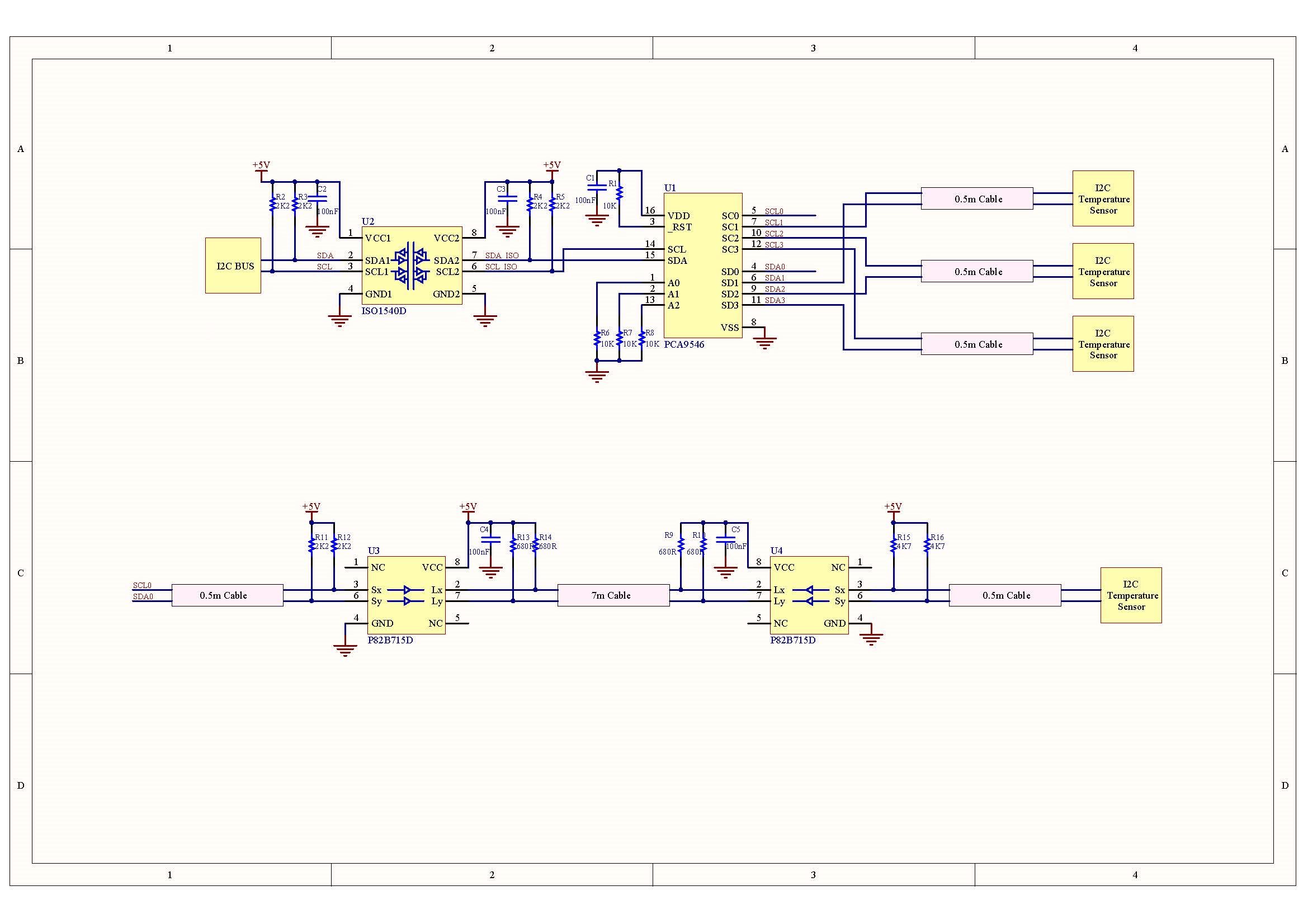
In my project I use a micro controller to read 4 I2C temperature sensors that have the same address

So  I have an ISO1540 to isolate the bus, and a PCA9546 (4 channel switch).

The three sensors are connected through 0.5meter cables and the fourth with a 7 meter.

Because of the cable length the fourth sensor didn't work so I decide to use two P82B715 to extend the bus.

But still can't read data.

Attached you can see the schematic diagram and the signals of the PCA9546 output and sensor input.

Any suggestions?

Thanks in advance

  • Hi Harris,

    Thanks for summarizing your issue clearly. I don't see any schematic issues, and just looking at the waveforms it seems like what you are getting at the temperature sensor input basically matches what you are sending down the cable (at the PCA9546 output). Are you not seeing a response back from the sensor at all? Or, are you getting a response but it isn't properly received at the master side? What are the VIH and VIL requirements for the sensor and for the I2C master being used? (I ask about VIL requirements in particular since it looks like the low level at the sensor input is a little high - maybe 500 mV or so. This could be improved by increasing the pull-up resistances used.)

    I assume communication is working with the three other sensors that connect via short cables - is that correct? I noticed that your schematic does not show a pull-up resistance on those connections - is that contained elsewhere? (PCA9546 should require a pull-up resistance on both sides in order to function properly.)

    Regards,
    Max
  • Hi Max

    Thanks for your quick reply

    About the sensor with the long cable, i don't get any response back.

    The other sensors are working fine (they do have 2k2 pull up resistors, i just didn't put them to the schematic - I wanted to focus to the circuit with the P82B715)

    The VIH and VIL, for the master are VIL<2.1, VIH>2.6, I can't find these specs for the sensor. I changed the pull up resistors at the side of the sensor, from 2k2 to 10k and 20k but nothing changed.

    Should I increase the values of the pull up resistors of the Lx, Ly also?

    I also measured the signals to the sensor with the sort and the long cable and the only differences are:

    Vmin (the negative spike): sort cable -> -100mV, long cable -> -1.72V.

    Fall time: short cable -> 55ns, long cable -> 80ns

    Rise time: short cable -> 800ns, long cable -> 590ns

    Regards, Harris

  • Hi Harris,

    Since the output of the P82B715 looks OK, I'm not sure you would get much benefit from modifying the pull-up resistances on the Lx/Ly lines. Did you at least see a lower "low" level voltage when you increased the pull-ups, though? I want to make sure you got something low enough (say, < 400 mV) that it would not be an issue for most slave devices.

    Could you please check both the SCL (clock) and SDA (data) lines on the scope? It's possible that the longer cable is introducing some skew between these lines that is preventing the sensor from properly registering the I2C commands.

    It might be helpful to compare the sensor inputs for the long-cable case to the (working) short-cable case to see what the difference is as well.

    Max
  • Hi Max

    I did manage to get response from the sensor. What I did was to replace the 7m cable with a shielded one.

    I still don't know why the previous one didn't work, because the signals of data and clock were almost identical (comparing with the short cable) and also the VIL was below 400mV.

    I will make some more tests to try to find the reason.

    Thanks a lot for your support

    Regards, Harris

  • Thanks for the update. One other thing to check would be the grounding. Since I2C uses single-ended (ground-referenced) signaling, the grounds of the master-side and slave-side should be close to the same potential in order for communication to work. If you aren't running a ground wire out to the sensor, you should try that.

    Max