Other Parts Discussed in Thread: ALP
Hi E2E members
I asked the following question.
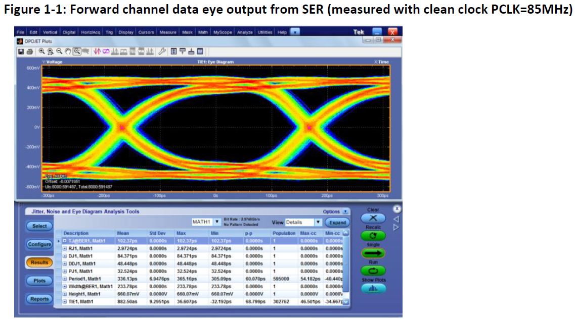
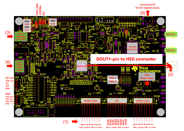
- How to measure the waveform of FPD-Link III output
e2e.ti.com/.../744023
I have more 2 questions about eye diagram.
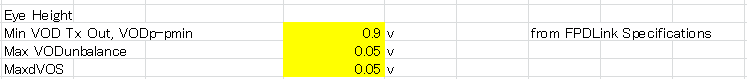
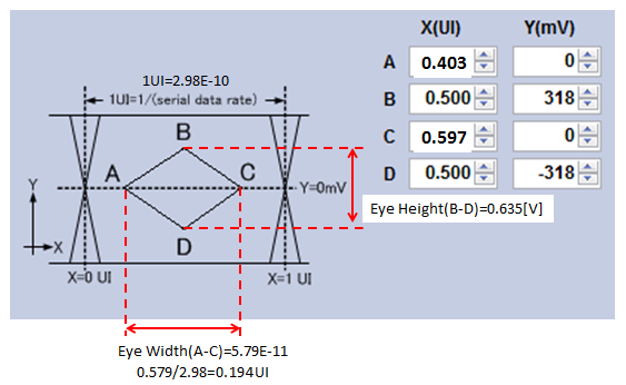
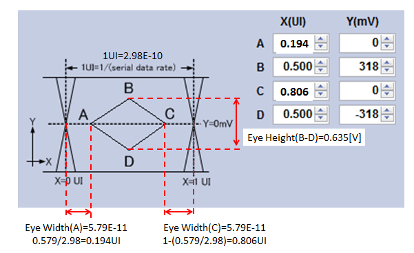
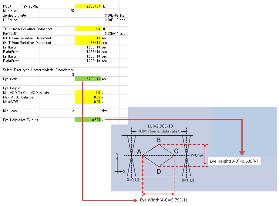
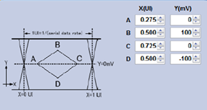
1. Do you have Eye Mask setting of measuring the eye diagram?
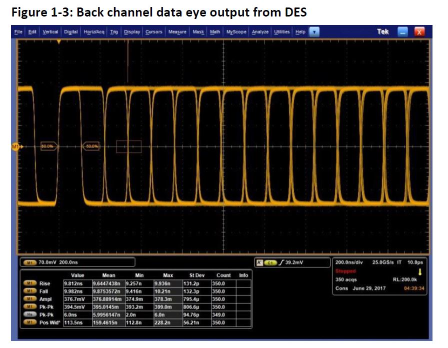
2. I think FPD-Link output have back-channel data.
so, can we measure the eye diagram of image data signal?
Is there a thing i should pay attention to measure the eye diagram?
Regards,
Nao