This thread has been locked.

If you have a related question, please click the "Ask a related question" button in the top right corner. The newly created question will be automatically linked to this question.

TPS65987DDJ: TPS65987DDJ configuration regiest setting for voltage swap

Part Number: TPS65987DDJ
Other Parts Discussed in Thread: TPS65987D, TIDA-050012, TIDA-050014

Hi Sir,

In our case, we want to switch the voltage of type-c adapter from 20V to 12V.

What is the mapping configuration register of TPS65987DDJ ?

The commanded from EC through I2C1 to TPS65987DDJ. 

Regard.

Nathan

  • Hi Nathan,

    Would you first be able to tell me what system this will be going into? Is this being designed into a Thunderbolt platform or a monitor?

  • Hi Adam,

    We support the dual role port(prefers power source) , DP mode and don't support thunderbolt.

    We want to change PDO profile setting from PDO2 20V to PDO3 12V on S5 states from EC.

    How about the modify rule and register on TPS65987DDJ ? 

    Regards,

    Nathan


  • Hi Sir,

    After Hand-Shake Process,Our customer Want to change the Voltage 20V-->5V or 12V,

    How should we through I2C register to change voltage?

    Hugo

  • Hello,

    First, the TPS65987DDJ is only intended for Thunderbolt applications and monitors. Since your system is neither of these, you must use the TPS65987D.

    As far as changing the source voltage, is there a specific reason why they are wanting to change from a high voltage contract to 5V or 12V?

  • Hi Adam,

    Please check following information.

    DRP, sink configuration,

    PDO1-

    Operating 0.9A

    Fixed 5V

    Fixed sink

    Maximum 3A

    Minimum 0.9A

    PDO2-

    Operating 0.9A

    Minimum voltage 5V

    Maximum voltage 20V

    Variable sink

    Maximum 3A

    Minimum 0.9A

    Power voltage currently :

    System on : VBUS =5V(negotiate)->20V

    System off : VBUS =20V

    Target power voltage:

    System on : VBUS = 5V(negotiate)->20V

    System off : VBUS = changed from 20V to 12V

    Reason : for more power saving while system off

    Question : If we need to create PDO3 for maximum =12V?

    If yes, how to change the PDO#?

    Regards,

    Nathan

  • Hi Nathan,

    Then you will need to make a configuration to where you have a high or low signal connected to a GPIO trigger a new configuration being loaded into the system. You will use the app config feature to accomplish this. The following TI design and app note should help you out. Look at section 3.2 of the app note

    https://www.ti.com/tool/TIDA-050014

    https://www.ti.com/lit/an/slvae11/slvae11.pdf

  • Hi Adam,

    Thanks for your suggestion.

    There are some questions after study app note.

    What kind of Mapped Event setting for GPIO4 ?

    And our transmit sink capabilities table as below.

    Please help double confirm it.


    When the GPIO event is high that transmit sink capabilities is 12V.

    When the GPIO event is low that transmit sink capabilities is 20V.

  • Hey Nathan,

    I would recommend downloading the following configuration tool. It includes the project file for the Power DUO Source and Sink boards. You can load these projects by clicking Project -> New Project -> TPS65987DDH -> TIDA-050012 Source Board. This is a great example of how to use the App Config functionality.

    http://www.ti.com/tool/TPS6598X-CONFIG

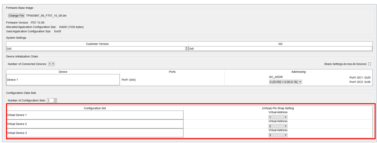
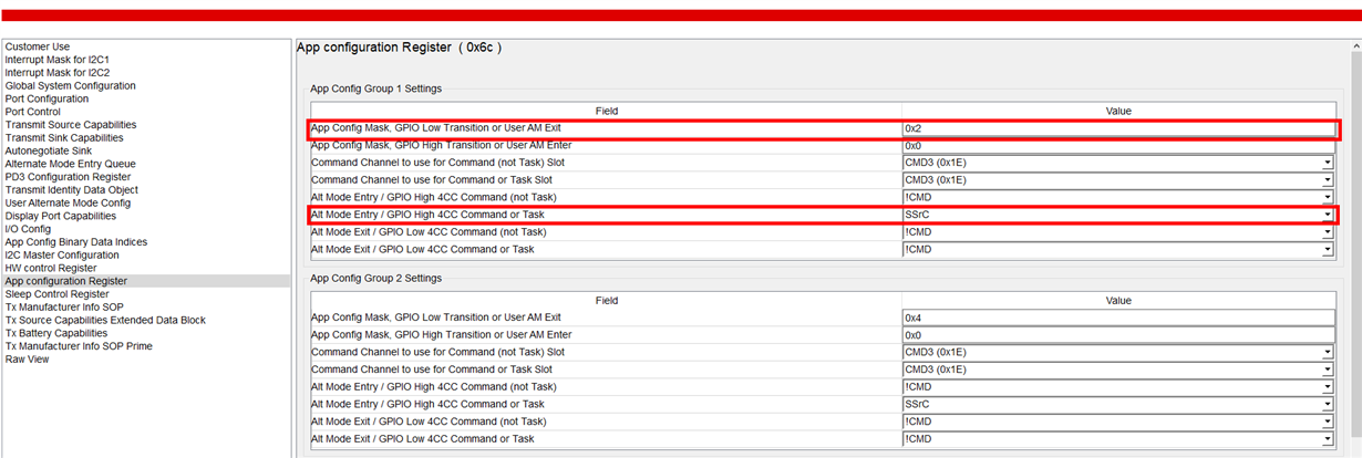
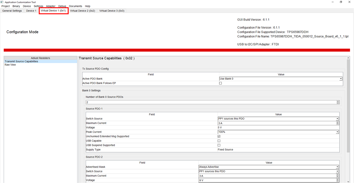
    First you create the number of virtual devices that you need for your application. Then for each virtual device, you create and assign an event either on the rising edge or falling edge of the signal to the GPIO. In the highlighted second image, the first virtual device is connected to app config group setting 1, and on a rising edge, the source capabilities are sent again on the CC channel with the new capabilities. For the GPIO setting, use 'Port 0 Load App Config x Event'

  • Hi Adam,

    Our system is notebook and sink only.

    The power is supplied by a thirty party Type-C adapter( 5V, 9V, 12V , 20V ).

    We want to change the supplied power voltage from 20V to 12V when system in light loading.

    Please show us the setting example.

    Thanks.

    Nathan

  • Then you can use the PWR DUO Sink configuration template as an example. Please refer to my previous post, but instead of clicking TIDA-050012 Source Board, you would click on TIDA-050012 Sink Board.

    You would the virtual devices to advertise its sink capabilities of going up to 12V

  • Hi Adam,

    I have referenced the TIDA-050014 Sink board design example and completed the swap voltage function (from 20V to 12V).

    We used  GPIO14 to trigger event signal from LOW to HIGH and created one virtual devices to advertise its sink capabilities of going up to 12V.

    We have some question for the examples of the TIDA-050014 Sink board design.

    1. After the function completed for swap voltage from 20V to 12V.

        Can we use the same GPIO14 to reduction swap voltage from 12V to 20V (trigger event from HIGH to LOW)?

  • Hi Nathan,

    Yes that should be fine. If you have one configuration to load on a falling edge and the other configuration to load on the rising edge, that should work for your application.

  • Hi Adam,

    Please help to confirm the setting in following graph.
    To building Virtual Device 2 (Mask 0x8) and set it up to App Config Mask, GPIO High Transition or User AM Exit. (Value 0x8)
    Then the PD is shutdown not any power output. When the system power on.

    [/quote]

    Nathan

    Regards,

  • Hi Nathan,

    Yes this looks correct and should accomplish what you are wanting to do.

  • Hi Adam,

    We want to used one GPIO to swap voltage from 20V to 12V and reduction from 12V to 20V.

    Function status as below:

    1. GPIO14 --> set internal pull down --> Mapped event port 1 load app config 1 event "App Config Mask GPIO LOW Transition or User AM Exit" --> Mapped virtual device 1 (0x2)  <<<  20V ->12V function ready

    2. Set GPIO14 Mapped event , port 1 load app config 1 event "App Config Mask, GPIO HIGH Transition or User AM Exit" --> Mapped virtual device 1 (0x8)  <<<  12V ->20V  The system can't power on.

    Nathan

  • Would you be able to elaborate on what you mean by "system can't power on"? Are you not able to charge at the 20V, or does nothing happen when you make the GPIO high transition?

    Also what is the state the system is in before you make the GPIO High transition? Is the charger already attached and you are wanting the PD controller to negotiate a higher voltage?

  • Hi Adam,

    We have two test result.
    Test A
    (App Config Mask GPIO LOW Transition or User AM Exit --> Mapped virtual device 1 (0x2)) 12V
    (App Config Mask, GPIO HIGH Transition or User AM Exit --> 0x0 )
    Step 1. flash new PD FW and plug-in type-C adapter to power on the system.
    Step 2. The GPIO14 "internal pull down" and make the GPIO14 signal from low to high from EC that the PD can swap voltage from 20V to 12V.
    Step 3. When the PD out voltage is 12V and make the GPIO14 signal from low to high from EC that nothing happen the PD output still is 12V.

    We want the voltage to return to its original state of 20V.

    Test B
    (App Config Mask GPIO LOW Transition or User AM Exit --> Mapped virtual device 1 (0x2))12V
    (App Config Mask, GPIO HIGH Transition or User AM Exit" --> Mapped virtual device 2 (0x8))20V
    Step 1. flash new PD FW and plug-in type-C adapter to power on the system.
    Step 2. The PD controller The PD controller has no output voltage.

    So Can we switch the ouput voltage of the PD controlle from 20 -> 12 -> 20 to use a GPIO ?

    Regards,
    Nathan

  • Hello Nathan,

    Would you be able to use a separate GPIO for each event, similar to what the power duo board did? So instead of using the rising edge for one command and the falling edge for the other, you would use both the rising and falling edge for each configuration, having their own respective GPIO's

  • Hi Adam,

    Yes, I have used a separate GPIO for each event and follow the sink power duo board setting. but still have some question.
    1. When only one set of events (The PD default 20v output when system power on. Set event to GPIO14 to get 12V output). --> The function ok.
    2. To add a second group of events (The PD default 20v output when system power on).
    set the GPIO14 for 12V output.
    set the GPIO15 for 20V output.
    The PD 65987DDH do nothing. The VBUS is keep 5V.


    Do you have any suggestions for us to check for PD FW setting.

    Regards,
    Nathan