This thread has been locked.

If you have a related question, please click the "Ask a related question" button in the top right corner. The newly created question will be automatically linked to this question.

TPS65982: Actual EXT, HV and 5V current measurement with ADCs read operation.

Part Number: TPS65982
Other Parts Discussed in Thread: BQ25713

Hi guys,

thanx in advance for assistance.

I need measuring an actual current flows through TPS65982.

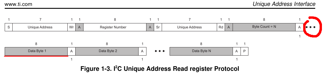
I've programed an I2C read\write algorithm:

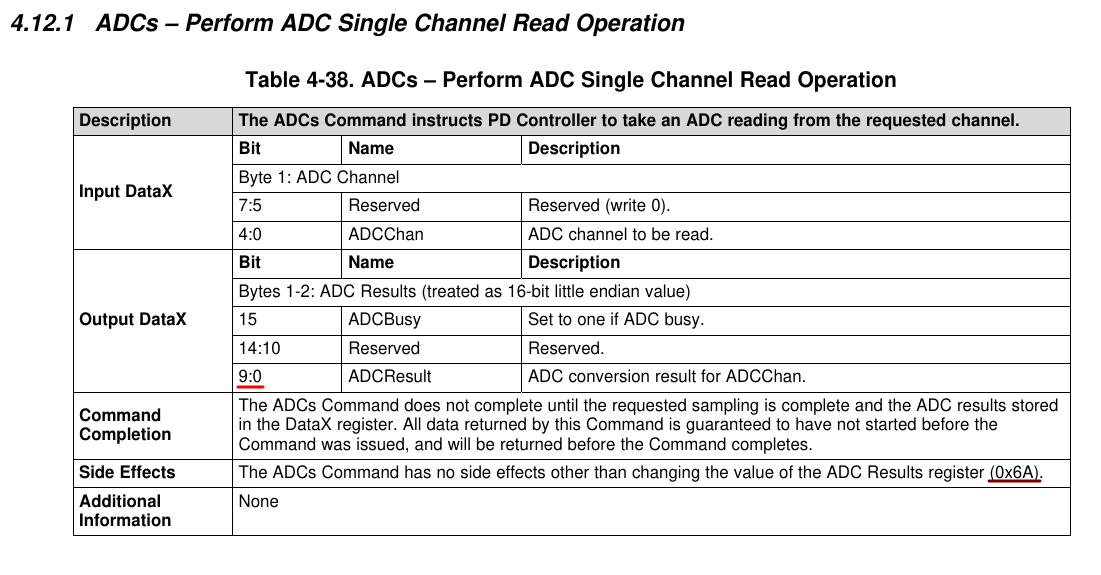
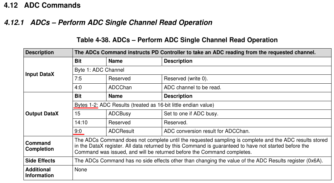
  1. 4CC ADCs command to Cmd1 (0x08) + 1 byte according ADC channel (0:4 bits) to Data1 (0x09) register
  2. Cmd1 (0x08) reading to be compared with following things: whether result is equal to "ADCs" the command is processing now, if "!CMD" so that I have an error and whether it's equal to "\0\0\0\0" the ADCs command has been processed
  3. reading the 2 bytes result from Data1 (0x09) register
  4. if bit 15 (ADCBusy) is one the step #3 is performing again
  5. if bit 15 is zero the ADC measurement result is getting masking to 0:9 bits

An important point: I didn't find any manual descripting ADCs read operation's channels enumeration list. I've used "TPS6598x Application Customization Tool" taking there a drop-down list of ADCs channels.

According the list's items order the channels enums are:

PP_EXT_CURRENT = 3

PP_HV_CURRENT = 5

PP_5V_CURRENT = 7

I've passed them in step #1.

Having no USB devices plugged into USB-C port I was getting results kind like these:

PP_EXT 0

PP_EXT 256

PP_EXT 512

PP_5V 512

PP_5V 256

PP_5V 0

PP_HV 0

PP_HV 512

PP_HV 256

I'm confused of these two fixed 512 and 256 values.

So my questions:

1) Did I use the ADCs channels' enums right? Whether I didn't please point me to a needed article of TI document?

(slvuan1a.pdf doesn't disclose this info)

2) Why the ADC results are those fixed ones (256 and 512)?

  • Hello Yevhen,

    The expert covering this device is located in India so please expect a delay in response. Thanks in advance for your patience.

  • Hi 

    The channels (3, 5, 7) which you are reading are correct. 

    When the switches are not enabled, ADC returns garbage values. So, please ignore ADC values when the switch is not enabled. 

    Thanks

    Prajith 

  • Prajith Cheerakkoda

    Thank you for the reply.

    I'll approve my issue as fixed after some tests.

    Can you tell what a document did you use getting know the information about "ADCs" ADC channels? Or is it only of personal practice experience?

  • Prajith Cheerakkoda

    I've tested "ADCs" reading with SNK device plugged in and SRC charging device plugged in.

    The same results and "768" is getting sometimes.

    "When the switches are not enabled..."

    1) Should I enable the switches in any way? Or would it be enough if PD contract is active and a current is flowing?

    Red underline: 2 ^ 10 = 1024 is too small to display all kinds of current could be.

    2) Should I use any coeff.? Or would any V(ref) be used in calculation of the result?

    Maroon underline of the 1st and the 2nd screenshots: 

    3) Can 0x6A be read properly at all?

    So, these 3 qeustions...

    Thanx in advance.

  • Update:

    Question 2 is answered:

    https://e2e.ti.com/support/interface/f/138/t/635918

    "13.1 ADC" provides the equation.

    ----------------------------------------------

    In my project I have BQ25713 and TPS65982 on a bus. I had plugged MacBook into my testing PCB setup. I had measured IADPT (BQ25713 ADC value) current and I had got "ADCs" read result of HV_EXT channel. I was comparing these two measurement values at about the same times. I have to say that results have been disparates, e.g.:

    TPS65982 ADC(dec) TPS65982 ADC EXT channel result (A) BQ25713 IADPT (mA)
    0 0 0
    0 0 42
    768 4,50439882697947 996
    768 4,50439882697947 1488
    512 3,00293255131965 767
    512 3,00293255131965 849
    512 3,00293255131965 1036
    512 3,00293255131965 946
    256 1,50146627565982 1027
    256 1,50146627565982 1199

    So, questions 1 and 3 remain unanswered for me. I would only add to the first one "What could I do wrong with my "ADCs" measurement described in post#1?"

    Thanks in advance.

  • Hi,

    Based on the internal discussion, ADC use is limited to the PD FW. We suggest you to use an external current sensor for other uses.

    Thanks

    Prajith  

  • Guys, an unexpected discovery.

    I had put Saleae Logic Analyzer on the I2C bus when I was reading PP_EXT_CURRENT channel with "ADCs" command from "TPS6598x Application Customization Tool". Aardvark device was used.

    Setting EXT switch as ADC channel parameter, performing "ADCs" read operation.

    Setup Write to [0x7E] + ACK
    0x09 + ACK Data1 register
    0x01 + ACK length
    0x03 + ACK EXT channel
    Setup Write to [0x7E] + ACK
    0x08 + ACK Cmd1 register
    0x04 + ACK length
    0x41 + ACK A
    0x44 + ACK D
    0x43 + ACK C
    0x73 + ACK s

    Checking "ADCs" command execution state (command processed cause zeroes returned), reading ADC result (Aardvark does it twice one by one).

    Setup Write to [0x7E] + ACK
    0x08 + ACK Cmd1 register
    Setup Read to [0x7F] + ACK
    0x04 + ACK length
    0x00 + ACK 0
    0x00 + ACK 0
    0x00 + ACK 0
    0x00 + NAK 0
    Setup Write to [0x7E] + ACK
    0x09 + ACK Data1 register
    Setup Read to [0x7F] + ACK
    0x40 + ACK 64 bytes len
    0x03 + ACK ADC ch 3
    0xC3 + ACK Data1 result LSB
    0x00 + NAK Data1 result MSB

    Please look at red marked line. Data1 register reading result keeps the channel number.

    I haven't expected this byte is presented in the message at all. So I've parsed the needed result beginning of it but not beginning of Data1 result LSB.

    How could a developer know this not debugging?

    You can see bytes count starts with 1st which keeps LSB of ADCResult and not with any zero byte keeping ADC channel number.

    Only three dots could implicitly hint that something could be before 1st byte:

    OMG :-(

    So I have got the answers for my questions.

    Data1 result LSB
  • The last point I have unclarified is why I could get output current results only while a power consumer is connected to USB-C port. And I can't get input current real values except zeroes when a charging device is connected to USB-C port.

    I've checked this fact with Logic Analyzer and yes, I'm getting zero values in LSB and MSB:

    Setup Write to [0x7E] + ACK
    0x09 + ACK
    Setup Read to [0x7F] + ACK
    0x40 + ACK
    0x03 + ACK
    0x00 + ACK
    0x00 + NAK

    So please tell me what reasons could be to not receive this real values in this case?

  • I tested "ADCs" reading with Aardvark when a 87W Apple charging device was supplying a setup test board.

    And as in the case with my SW measuring the Aardvark detects a zero current on EXT switch channel after "ADCs" has performed.

    So I'm updating my questions to the last ones:

    1) Could an input current be measured on TPS65982 at all?

    2) Whether it could what mandatory settings have to be applied to its configuration?

    Thanks in advance.

  • Hi,

    Please find my response below.

    1) Could an input current be measured on TPS65982 at all?

    >>> No, current measurement with ADCs is possible only when the Power Path is enabled AND the port sourcing power. 

    2) Whether it could what mandatory settings have to be applied to its configuration?

    >>> Please find response above. Configuration setting cannot change this behavior. 

    Thanks

    Prajith 

  • Thank you. The issue has been solved.

    P.S. I ask TI please add fixes to TPS65982 Reference Manual about returning by "ADCs" via DataX also the measured Channel number before a ADC(dec) value. Cause it's a real issue which wastes a developer time while he\she's debugging to find a reason.

  • Hi,

    As I mentioned in my previous post, ADC use is restricted to the PD FW. We will consider removing ADC related info from TRM in the next revision. 

    Thanks
    Prajith