This thread has been locked.

If you have a related question, please click the "Ask a related question" button in the top right corner. The newly created question will be automatically linked to this question.

The PHY chip DP83620 doesn't work after reset

Other Parts Discussed in Thread: DP83620, DP83630

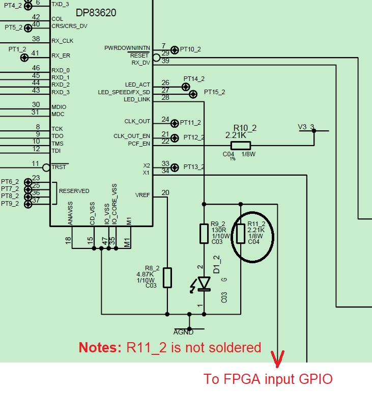
After I reset the DP83620(give the pin29:RESET_N low level for 2ms) , the PHY didn't work. If I reset it again, it will recover.

The three signals RX_DV, RXD_0, RXD_1 which are all low level means there is no valid output. This means PHY chip didn't implement the communication function at this time. So, it seems like the PHY chip is in dead status.
I also read the PHY Status Register (PHYSTS) on DDU and it's 0x0004 which means "Link not established".

This issue happens occasionally. So I wonder in what situation the PHY chip will like this( in dead status) and how to avoid this?  Thanks!

  • Hello,

    Do you see differences in the strap settings of the DP83620 between a good reset and a bad reset, i.e. do register reads change in bits that rely on bootstraps? 

    Do you see the same behavior when a Full Software Reset is applied, what about a Soft Reset?

    Regards,
    Justin 

  • Hello Justin,

    Thanks for your reply.

    1. How to see strap settings of the DP83620?  Is there a register that could see all the settings? I haven't done this before, so please tell me more details.

    2. After Soft Reset, strap settings will also be reinitialized, right? And the strap settings are also determined by strap  option pin assignments like when power-up?

    3.Is Soft Reset function  implemented by assign bit9=1 in PHY Control Register 2 (PHYCR2)? How do I assign the value of other bits in PHYCR2? Please give me a specific example on how to set the soft reset.

    Thanks! 

  • Hello,

    1. There is not a single register that will describe all strap settings of your device but the strap setting can be found in register descriptions with "Strap" written in the default state of each bit description. 

    2. A Soft Reset will not reinitialize the strap settings as it will keep the existing register settings unchanged. The strap settings of the device will be determined at power-up or hardware reset. 

    3. A Soft Reset can be implemented by writing register 0x1C=0x0200. This is the hexadecimal representation of 0000 0010 0000 0000 

    Regards,
    Justin 

  • Hello Justin,

    Thanks very much and I will try it out with your guide.

  • Hello Justin,

    I have two questions:

    1. I tried the soft reset by writing register 0x1C=0x0200,  and I read the PHYSTS register which is 0115.  Normally it is 0715 while after the soft reset it is 0115. Is 0115 is OK? 

    2. Can I also use the full soft reset, which wirte register 0x00=0xB120, I also get 0115. Which reset(full or partial) should I use?

    Thanks!

  • Hello,

    The difference between PHYSTS (0x10) = 0715 and 0115 is that bits [10:9] are latch-low and should be read twice to determine if they will match the normal 0715. 

    Either reset can be used. The original problem is related to the pin-reset that causes the PHYSTS register to show no link. Can you describe how often the RESET_N low reset results in a bad state and confirm that the software resets do not show this behavior?

    Further, please read the following bits when the device is in normal operation and compare to when the device after a bad reset: 

    Register Bit
    00 13

    00

    12
    00 8
    04 8
    04 7
    04 6
    04 5
    16 6
    16 3
    16 1
    17 14
    17 5
    19 5:0
    1C 1
    1F 0
    16 0

    Regards,

    Justin 

  • Hello Justin,

    I tried to read out the register when the device is in normal operation and compare to when the device after a bad reset:

    The differences are in the four bits, could you please help me anylyze what's wrong with the bad reset? Thanks very much!

    Normal:   reg00[15:0]=0x3100;   reg04[15:0]=0x01E1; 

    Bad reset: reg00[15:0]=0x2100;  reg04[15:0]=0x0101; 

    Register Bit

    00

    12
    04 7
    04 6
    04 5

  • Hello,

    Based on the differences you've highlighted above, it appears that after a "bad reset" the DP83630 is in a mode with auto-negotiation disabled and forced into 100BaseTX Full Duplex. Can you provide the schematic for this application? I would focus on the LED_LINK (pin 28) strapping scheme as that seems to be the difference between a good reset and a bad reset.

    Regards,
    Justin 

  • Hello Justin,

    Thanks for your reply.

    1. Pin28 is connected to three items as showed in picture: The first is R9_2; The second is R11_2 (This resistor is not soldered and left open); The thrid is FPGA input I/O (FPGA read the voltage level of LED_LINK).

    Another notes: There are 10 PHY circuits which use  the same circuit design on my board while only the eighth PHY chip has this issue. 

    2. Could please explain why disabled  auto-negotiation  could cause PHY chip not to work? Thanks!

  • Hello,

    What is your desired mode of operation, in terms or speed and auto-negotiation? 

    The concern I see is that if you are relying on strapping an LED pin to the non-default state, there should be a parallel strap resistor to control the voltage at the pin at the time of reset. 

    If you want to disable auto-negotiation, I suggest populating R11.

    If you want to enable auto-negotiation, the best design would be to configure the LED to work in active low (as opposed to the active high configuration you have now). A debugging effort you could try is to depopulate R9 and determine if the problem persists.

    Regards,
    Justin 

  • Hello Juston,

    I want PHY works in 100Mbps, auto-negotiation enabled. When in normal operation, LED (D1_2 ) is off and if not work, D1_2 is on. 

    So I need to use R9_2 and D1_2 in series and connected with Pin28.

    Is this circuit OK? Will it be risky on uncertain status for Pin 28 when hardreset?

     Thanks!

  • Hello,

    Since you are relying on the internal Pull-up resistor to strap the pin to Auto-negotiation enabled, the LED_LINK pin will be set in active low mode. That means that if you have link you the pin is "ON" driving the pin low when link is good. 

    The configuration on your schematic is not recommended because when the link is up and LED_LINK is being driven low, the pin will transition from driving low to being pulled up by the internal strap, and could be causing the intermittent reset behavior you are seeing. 

    I recommend removing R9 and D1 as a debugging exercise and checking if the problem is resolved, link can be checked through register. 

    Regards,

    Justin 

  • Hello, Justin

    Thanks very much!

    Please close the case.