This thread has been locked.

If you have a related question, please click the "Ask a related question" button in the top right corner. The newly created question will be automatically linked to this question.

TPS65987D: Switching Configuration data sets

Part Number: TPS65987D
Other Parts Discussed in Thread: TIDA-050014

Dear Sir/Mam,

I made a custom board using the TPS65987D.

Now I use the Application Customization tool to create a flash image for it. I used the existing TIDA-050014.pjt as a template. 

At this stage I need a sink-only configuration, which will accept any source, from 5V to 20V.

Since I don't have spare GPIOs to use, I need to make some I2C writes with the external microcontroller, which will configure the TPS65987D to inform the charger to apply high voltage at the bus.

As with the template, I've got 3 Configuration data sets, the question is how do I switch them without the GPIO. I thought it can be done with User Alternative modes, but with any configuration I tried my attempt to issue [AMEn] command gives me REJECT_CMD return status. What am I doing wrong?

Please help!

Thanks a lot and Best Regards,

Boris.

  • Hello Boris,

    If you would like to mirror the functionality of TIDA-050014 and load different configurations based on external events, then you must use GPIOs to control this. You cannot load any of these configurations using I2C commands, and can only be done via GPIO

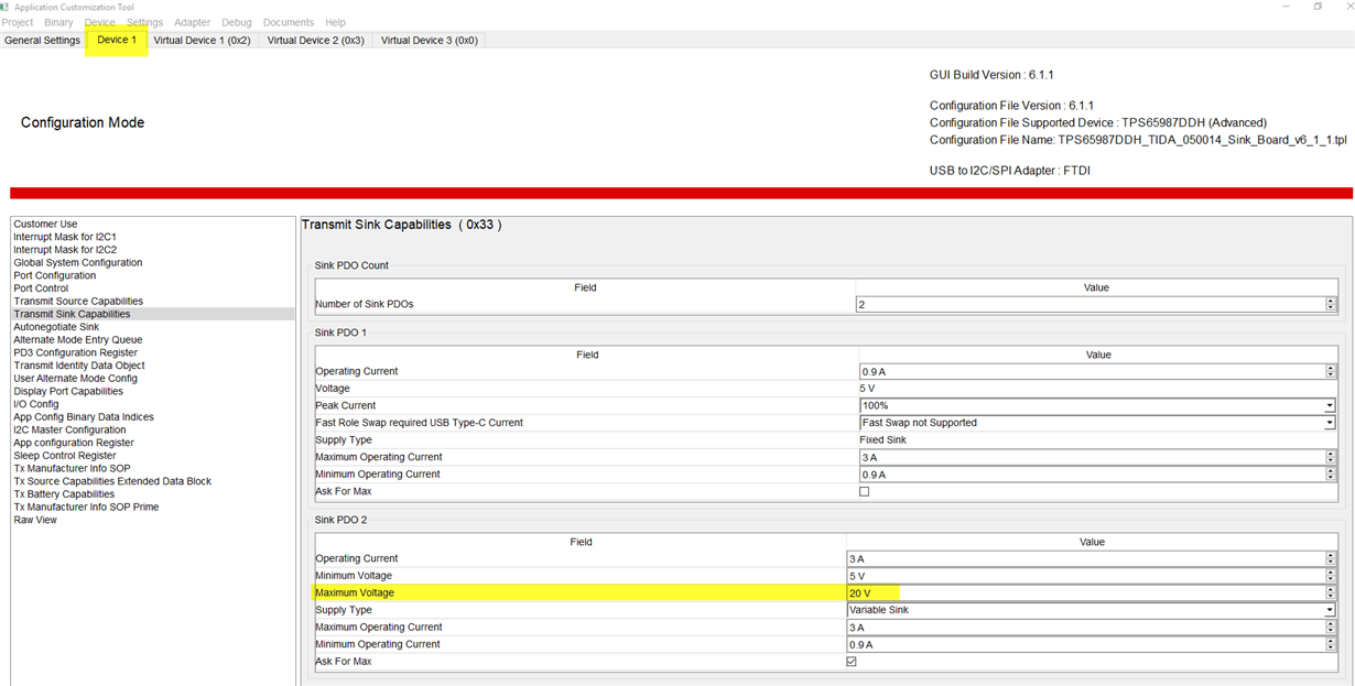
    However, if you would like the TPS65987D to sink up to 20V all of the time, then just change the default sink capabilities from only transmitting 5V to being able to sink up to 20V 

  • Hello Adam,

    Thank You for the answer.

    As far as I understood, there are few configuration sets, the default is fixed sink of 5V, which I cannot change. I may create the second set (virtual device?), define it as a variable sink with 20V maximum, which is OK for my application. The only thing I still do not understand is how to load this configuration set automatically without GPIO. Or should there be anothey way to go?

    Thanks a lot and Best Regards,

    Boris.

  • "The default is fixed sink of 5V, which I cannot change"

    • False. You can have a configuration where it always advertises sink capabilities up to 20V. The purpose of the power duo design is to showcase how you can have multiple configurations that can be saved and loaded depending on the polarity of a GPIO. Using the application configuration tool, register 0x33 controls the sink capabilities that the PD controller transmits. 

    To summarize, if you want the TPS65987D to change the sink capabilities it advertises, then using the different configurations is the correct approach. However, you can only load these through GPIO's like the power duo board does, not through I2C commands

    If you want the TPS65987D to always advertise 20V sink capabilities regardless of system conditions, then change the "device 1" sink capabilities to advertise 20V sink capabilities. 

  • Hi Adam,

    The settings You proposed worked well for me on the evaluation board, thanks a lot. However they do not work on my own hardware by some reason. May I continue with the questions related to my own design in this thread or should I open a new one?

    Best Regards,

    Boris.

  • Hello Boris,

    You may continue to ask your questions in this thread, thank you for asking though 

  • Hi Adam,

    With the same firmware working on reference design I experience a problem on my own hardware:

    In case there is no battery present, TPS65987D turns on the powerpath switches, negotiates with the source for voltage, seems to work as intended.

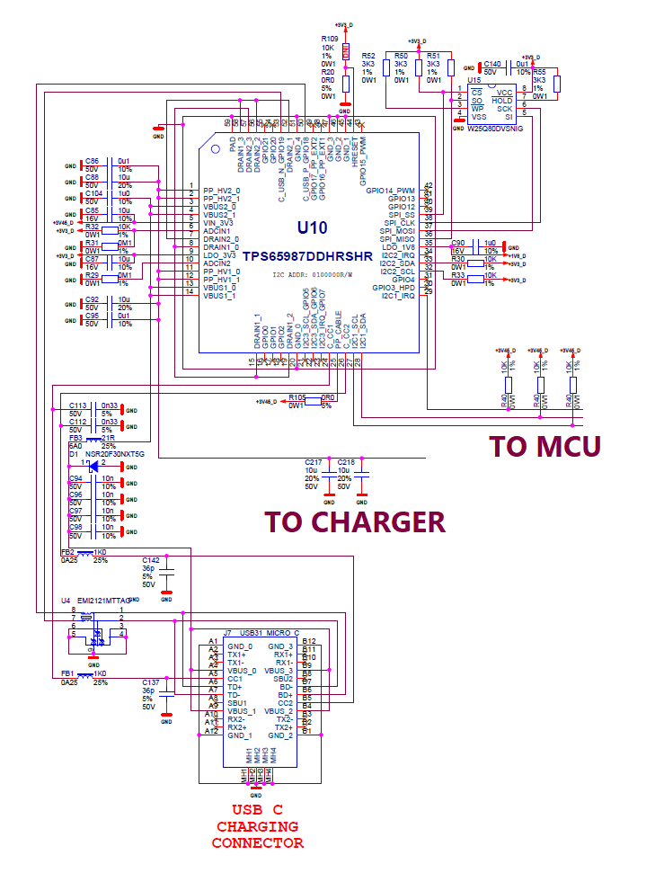
    If the battery is connected, (this means that 3.45V power supply is ON) the TPS65987D performs boot, can be accessed by a microcontroller through I2C interface, but never turns on the powerpath switches - PP_HVx pins are always at about ~0.1V level (leakage, I assume).

    Please see the schematic below. Can You please suggest what can cause such a behavior and which settings can I check for debug?

    Thanks a lot and Best Regards,

    Boris.
  • Hello,

    Are you saying that when the battery is connected to your system, and the TPS65987D is powered from VIN_3V3, the PD controller never closes the PPHV power path when a type-C source is connected?

    Is there a voltage on VBUS? If so, what is the voltage measurement on VBUS when PPHV reads 0.1V?

  • Hi Adam,

    Adam Mc Gaffin said:
    Hello,

    Are you saying that when the battery is connected to your system, and the TPS65987D is powered from VIN_3V3, the PD controller never closes the PPHV power path when a type-C source is connected?

    - yes, actually any source, from type-C PD from  TPS65987D reference design source to smartphone charger and even lab power supply. The TPS65987D behaved exactly the same way. The Vbus was around 5V, depending on supply, to be exact, from 4.9 to 5.2V. Everything changed when I removed R105. TPS65987D started to close the switches and even negotiated the correct voltage being connected to PD-type source. How does this correlate to the documentation? PP_CABLE (supplied by R105) is described there in one place as a supply to Vconn circuitry, in other place - it is written that it should be decoupled with a cap to ground without mentioning a supply, in a reference design (power duo) it is left floating at the sink and grounded at the source PCB. For now I see that TPS65987D does not negotiate 9V supply with the Samsung 5/9V charger (EP-TA20SBE), although gets from it 5V perfectly. I configured "BC1.2 and proprietary" in TPS65987D software, but the result is still 5V only. Where can I find an information which kind of proprietary chargers/protocols does TPS65987D support? Another thing I will test in few days is a dual roll port transition, since my device should work as a portable battery too.

    Best Regards,

    Boris.

  • Hello Boris, 

    Can you also share the project file you have flashed onto your system?

  • Hello,

    Your project file looks good to me and dont see any issues with it. 

    Re-reading your issue description with the Samsung phone charger, the problem only occurs with 9V and the PD controller is able to negotiate 5V properly. For an item like this, you really need a PD analyzer of some sort to read the messages sent between the two devices to determine if one of them is not behaving as expected. I typically recommend the Total Phase PD analyzer as it is not too expensive but still give you a lot of features/functionality. 

    There is not list of devices that the TPS65987D, but instead the idea that the TPS65987D is compatible with any USB-IF compliant device that is currently on the market. Having a PD analyzer would show what the source capabilities are that the charger is sending, the sink capabilities that the TPS65987D is sending, and why it never negotiates 9V.

    https://www.totalphase.com/products/usb-power-delivery-analyzer/

  • Hi Adam,

    Thank You for reviewing my project file and for PD analyzer recommendation, I will definitely purchase it and re-check all of the test cases with it.

    However my question was about one specific charger of Samsung, which is Qualcomm Quick Charge protocol-compatible.

    Is there a chance that TPS65987D supports Qualcomm Quick Charge? Or if not, will it support in the future (maybe by firmware update if possible)?

    Any other proprietary protocols (OPPO, Huawei, MediaTek, Vivo)?

    Best Regadrs,

    Boris.

  • Hi Boris,

    No, the TPS65987D does not support Qualcomm Quick Charge or any other proprietary Type-C charging schemes. The TPS65987D supports USB Type-C PD, and supports any compliant USB Type-C PD charger or device.

    So if the Samsung charger is not sending the 9 V support capabilities via USB Type-C PD messaging, then the TPS65987D will never negotiate the 9 V contract