This thread has been locked.

If you have a related question, please click the "Ask a related question" button in the top right corner. The newly created question will be automatically linked to this question.

DP83867IR: cannot Ping the IP address of the device

Part Number: DP83867IR

Hi team,

Problem Description:

when dp83867irrgz realizes 100m communication, phy and PC end self negotiate successfully, but PC cannot Ping the IP address of the device

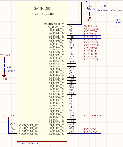
The hardware platform is the 7020 of the zynq7000 series of Xilinx. The dp83867irrgz (48pin) is connected with the PS terminal of the 7020.The requirement is to realize 100MHz network communication in rgmii mode only.

The schematic is as follows:

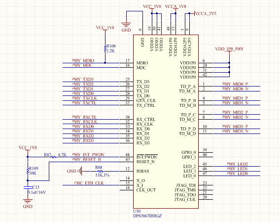
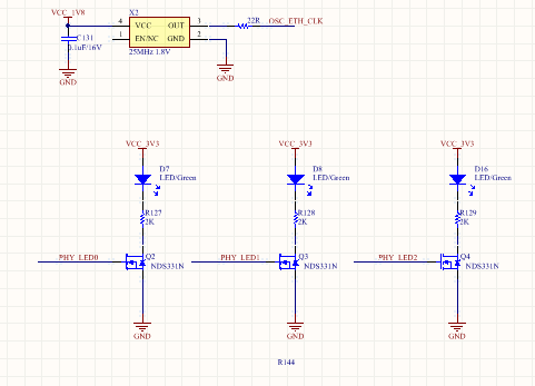
Strap pin only pin 38 (Rx_ CTRL) pull up the 5.76k resistor and pull down the 2.49k resistor to realize the automatic negotiation enable of Mode3, and other strap pins are open which in mode1

Through MDC and MDIO, the registers can be read and written normally. The register settings are as follows:

Read Register RegisterNum[0000] PhyData[1140]
Read Register RegisterNum[0001] PhyData[796D]
Read Register RegisterNum[0002] PhyData[2000]
Read Register RegisterNum[0003] PhyData[A231]
Read Register RegisterNum[0004] PhyData[0DE1]
Read Register RegisterNum[0005] PhyData[CDE1]
Read Register RegisterNum[0006] PhyData[006F]
Read Register RegisterNum[0007] PhyData[2001]
Read Register RegisterNum[0008] PhyData[6001]
Read Register RegisterNum[0009] PhyData[0300]
Read Register RegisterNum[000A] PhyData[0800]
Read Register RegisterNum[000B] PhyData[0000]
Read Register RegisterNum[000C] PhyData[0000]
Read Register RegisterNum[000D] PhyData[401F]
Read Register RegisterNum[000E] PhyData[00D3]
Read Register RegisterNum[000F] PhyData[3000]
Read Register RegisterNum[0010] PhyData[1140]
Read Register RegisterNum[0011] PhyData[6C02]
Read Register RegisterNum[0012] PhyData[0000]
Read Register RegisterNum[0013] PhyData[9CC0]
Read Register RegisterNum[0014] PhyData[29C7]
Read Register RegisterNum[0015] PhyData[0000]
Read Register RegisterNum[0016] PhyData[0000]
Read Register RegisterNum[0017] PhyData[0040]
Read Register RegisterNum[0018] PhyData[6150]
Read Register RegisterNum[0019] PhyData[4444]
Read Register RegisterNum[001A] PhyData[0002]
Read Register RegisterNum[001B] PhyData[0000]
Read Register RegisterNum[001C] PhyData[0000]
Read Register RegisterNum[001D] PhyData[0000]
Read Register RegisterNum[001E] PhyData[0002]
Read Register RegisterNum[001F] PhyData[0000]
Read Extended Register RegisterNum[0031] PhyData[10B0]
Read Extended Register RegisterNum[0032] PhyData[00D0]
Read Extended Register RegisterNum[0033] PhyData[0000]
Read Extended Register RegisterNum[0043] PhyData[07A0]
Read Extended Register RegisterNum[0055] PhyData[0000]
Read Extended Register RegisterNum[006E] PhyData[000E]
Read Extended Register RegisterNum[006F] PhyData[0100]
Read Extended Register RegisterNum[0071] PhyData[0000]
Read Extended Register RegisterNum[0072] PhyData[0000]
Read Extended Register RegisterNum[0086] PhyData[00A8]
Read Extended Register RegisterNum[00E9] PhyData[9F22]
Read Extended Register RegisterNum[00FE] PhyData[E721]

Debugging results:

1. LED0 is on, indicating that the link is established; LED2 flashes intermittently, indicating that data has been received or sent

2. It can be seen from the "Networking" of the task manager at the connected PC that the PC can discover the connection with the 100MHz network device, which indicates that phy and the link partner can negotiate successfully

3、RX_ CLK outputs 25MHz clock signal, RX_CTRL will produce 8321ns high level intermittently, other time is low level, RD0 ~ RD3 can also be measured waveform

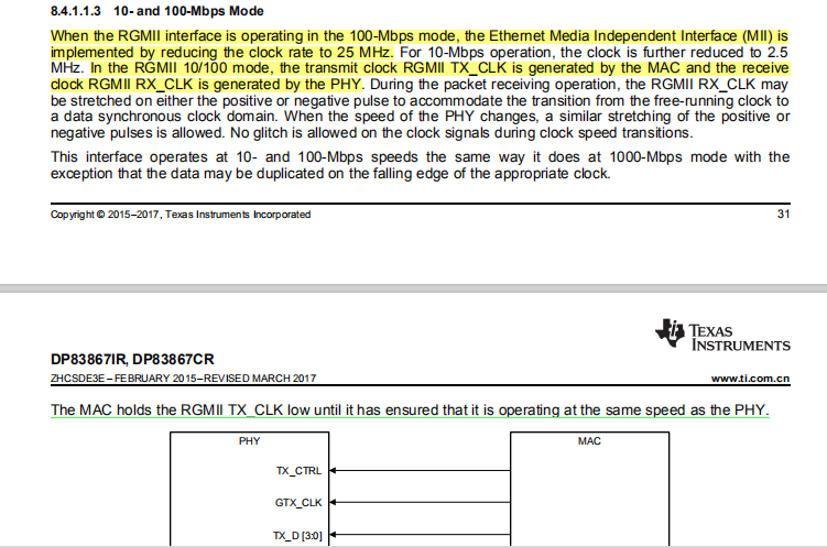
But GTX_ CLK has no signal generation, TX_ CTRL and tx0 ~ tx3 also maintain a certain level state. There is such a description in the manual, as shown in the underlined part below. But now GTX_ CLK has no clock signal.

Does it mean that MAC has not been at the same rate as PHY? Why not have the same rate? How can we achieve the same rate?

To sum up, the negotiation between phy and link partner is normal, but there seems to be no effective connection between phy and MAC. Because I am not familiar with 802.3 protocol, what kind of data frame should be between MAC and PHY? How to realize the communication between the two layers?

  • Hi Amy,

    The MAC should provide a TX_CLK matching the RX_CLK provided by the PHY. Is the zynq7000 MAC an FPGA implementation or dedicated MAC interface? 

    Can you also confirm if all FPGA pins connected to the PHY MAC interface have internal pull-up/pull-down states? Based on the SOR register 0x006E it appears the PHY ID of the device is 0xE, is that correct? Is this set through external strap resistors? 

    Regards,
    Justin 

  • Hi Justin,

    Thank you for your reply and make the following supplementary explanation for your asking:

    1\FPGA and ARM are integrated in zynq7000. MAC is the dedicated MAC interface of ARM end, and the pin connected to PHY MAC interface is tri-state interface, as shown in the figure below

    2、PHY_ ID is a little different from the theory. There is a little missing in the description of the problem. In fact, RXD0 (33pin) is the same as RX_Ctrl in pulling up 5.76k, pulling down 2.49k, and in Mode3, while RXD2 is open without pulling up / down. Theoretically, it should be PHYID3 = 0, PHYID2 = 0, PHYID1= 1, PHYID0 = 0. In fact, the voltage measured by RXD2 in the open state is 0.6V, and the PHY chip will judge it as Mode4, so the actual reading is PHYID3 = 1, PHYID2 = 1, PHYID1 = 1, PHYID0 = 0, and the value read in the register is 0x0e. Here, the measured voltage of RXD0 ~ RXD3 in open state is about 0.6V, is it a problem?

    3. Another thing that I don't quite understand is the difference between GTX_CLK and TX_CLK. The 48pin dp83867irrgz I chose only has GTX_ CLK pin, while 64pin IRPAP has GTX_ CLK and TX_ CLK。 Is it GTX_ CLK is 1000M clock, while TX_ CLK is a 10 / 100M clock? My main control chip only supports the MAC interface of RGMII, and the MAC dedicated  interface has only one TX_CLK. Does it mean that my main control chip can only connect with 48pin IRRGZ, but not 64pin IRPAP (because 64pin IRPAP needs GTX_ CLK and TX_ CLK)? The customer's current system is 100MHz communication under the RGMII interface. The customer would like to know if GTX_CLK is compatible with 10 / 100 / 1000MHz?

    sorry,I am not familiar with Ethernet Phys. Please point out the unclear description.

  • Hi Amy,

    2. Yes, I would say that the open state voltage on strap pins being 0.6V is problematic. This suggests there is some pull-up resistance provided by the MAC that is strapping the device into intermediate modes. Can you confirm only RXD[0:3] are affected by this? 

    3. The GTX_CLK is the RGMII clock provided from the MAC to the PHY in RGMII mode. This should match the RX_CLK frequency in RGMII mode. The TX_CLK in the 64pin device is the MII clock that is an output of the PHY in MII mode.

    REgards,
    Justin

  • Hi Justin,

    2. The customer measured TXD0~3、TXCLK、TXCTL、RXD0~3、RXCLK and RXCTL when RST pin is low. All signals are 0.6V. Should these signals be about 0V in theory?

    3. Can it be understand as: For 48pin devices, at 10M / 100M / 1000MHz communication rate, the GTX_CLK is 2.5M/25M/125M , and the clock is provided by MAC terminal; For 64pin devices, the clock is provided by TX_CLK at 10M / 100M, and GTX_CLK at 1000MHz?

    The customer wants to know what kind of waveform and amplitude of TXD0~3、TXCLK、TXCTL、RXD0~3、RXCLK、RXCTL between phy and MAC at 100MHz communication rate??

  • Hi Amy,

    2. TXD0~3、TXCLK、TXCTL、RXD0~3、RXCLK and RXCTL have internal pull-down resistors so if you want to utilize the default strap settings, the voltage at those pins should be near 0V, as specified in the Strap Resistor ratio tables in the Datasheet. If the voltage on the strap pins is 0.6V, the device will strap in mode 3 or 4 when VDDIO is 1.8V. 

    3. Yes, your TX_CLK descriptions for the 48 and 64 pin packages is correct. 

    At 100Mbps speed, RX_CLK and TX_CLK operate at 25MHz with an amplitude near the VDDIO setting. 

    Regards,
    Justin