This thread has been locked.

If you have a related question, please click the "Ask a related question" button in the top right corner. The newly created question will be automatically linked to this question.

DP83849IF: PORT Switching: 'Normal Mode' (A-->A and B-->B) and 'Full Port Swap Mode'. (A-->B and B-->A)

Part Number: DP83849IF

Hi All,

Sorry for posting in a second thread but we have had no replies to the original thread for a dew days and hoped this might spur some new replies.

The original thread is here: e2e.ti.com/.../dp83849if-connecting-to-an-afbr5803-atz-fibre-transceiver-100base-fx

The idea is that at power-up the microcontroller (A PIC32MX795F512L) reads a switch setting and then sets the DP83849IF up accordingly.

Myself and a colleague (Jean-Michel) are trying to use the DP83849IF connected to a microcontroller on RMII port A switch between UTP connected to PHY A and Optical connected to PHY B.  

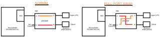
We have the UTP to RMII A (Normal Mode) working but cannot get the Optical connection on PHY B to RMII A (Full Port Swap Mode) working.

In 'Normal Mode' I have bits 9,10,11 and 12 of the RBR (17h) register set as 0000 for both PHY register sets and I see data on RMII A RXD0 (Pin 4)and RXD1 (Pin 5). And comms works!

In 'full port switch' mode I have bits 9,10,11 and 12 of the RBR (17h) register set as 0101 for both register sets. This is the suggested configuration for Full Port Swap. However,  I see nothing on RMII A RXD0 (Pin 4)and RXD1 (Pin 5).

Does anyone have any suggestions/ideas/things to try?

Thanks in advance,

Jean-Michel. & Clive

  • Hi Clive,

    1. When in 'full port switch' mode, is link established with the optical connection?
    2. If link is established, can you confirm that there are packets being sent out on the cable and to the PHY for the optical connection?
    3. Can you provide a two sets of register data for registers 0x00 to 0x1F? One set for when you are in 'normal mode' and one set for when you are in 'full port switch mode'.

    Regards,

    Adrian Kam

  • Hi Adrian,

    Thanks for your help. It is appreciated.

    First a little more information....

     When testing/developing I am using two configurations of hardware...

    UTP - 'Normal Mode'

    PC <---- utp ----> Target Board UTP (Phy A)

    Optical – ‘Full Port Swap Mode’

    PC<---- utp ----> Media Converter <---- Optical x 2 (TX and RX) ---> Target Board Optical (Phy B)

    Answers to your questions:

    1. In 'Full Port Swap Mode' I believe I have an optical connection. The Optical PHY (B) registers appear to indicate this. The Link LEDs on my Media converter are illuminated and are blinking. The media converter also has far-end-fault detection. This indicates all is OK.

    2. I am afraid that whilst I know I am sending the target board data in 'Full Port Swap Mode'  (I am pinging the target) I see no data on the target. I see nothing on the RMII A interface.

    3. Registers as requested...

    Address Full Port Swap Mode Normal Mode
    Copper
    (PHY A)
    Optical
    (PHY B)
    Copper
    (PHY A)
    Optical
    (PHY B)
    0  0x1000  0x2100  0x1000  0x2100
    1  0x7849  0x784D  0x786D  0x7849
    2  0x2000  0x2000  0x2000  0x2000
    3  0x5CA2  0x5CA2  0x5CA2  0x5CA2
    4  0x0DE1  0x0DE1  0x0DE1  0x0DE1
    5  0x0000  0x0000  0xCDE1  0x0000
    6  0x0004  0x0004  0x000D  0x0004
    7  0x2801  0x2001  0x2001  0x2001
    8  0x0000  0x0000  0x0000  0x0000
    9  0x0000  0x0000  0x0000  0x0000
    10  0x0000  0x0000  0x0000  0x0000
    11  0x0000  0x0000  0x0000  0x0000
    12  0x0000  0x0000  0x0000  0x0000
    13  0x0000  0x0000  0x0000  0x0000
    14  0x0000  0x0000  0x0000  0x0000
    15  0x0000  0x0000  0x0000  0x0000
    16  0x0000  0x0605  0x0615  0x0204
    17  0x0000  0x0000  0x0000  0x0000
    18  0x0000  0x0000  0x0000  0x0000
    19  0x0000  0x0000  0x0000  0x0000
    20  0x0000  0x0000  0x0000  0x0000
    21  0x0000  0x0000  0x0000  0x0000
    22  0x0100  0x014B  0x0100  0x010B
    23  0x0A21  0x0A21  0x0021  0x0021
    24  0x0000  0x0000  0x0000  0x0000
    25  0x8020  0x0021  0xB020  0x0021
    26  0x0904  0x0904  0x0904  0x0904
    27  0x0000  0x0000  0x0000  0x0000
    28  0x0000  0x0000  0x0000  0x0000
    29  0x6011  0x6011  0x6011  0x6011
    30  0x003F  0x089E  0x083E  0x089E
    31  0x0000  0x0000  0x0000  0x0000
  • Hi Clive,

    I do not see any glaring issues with the register values.

    Can you try the following experiments while in full port swap mode? This can help determine if the issue is on the MAC side or PMD side.

    1. Can you enable loopback mode in register 0x00 and see if you receive back the same packets that you send from the PC?
    2. Can you enable PMD Loopback in register 0x17 and see if you receive back the same packets that are sent from the target optical board?

    Regards,

    Adrian Kam

  • Hi Adrian,

    Thanks again for the reply!

    Sorry to ask, as you have probably guessed I am a bit of a newbie with some this stuff.

    In which register set (A copper or B optical) am I doing this?

    Don't forget I am only using RMII port A on the MAC side.

    If you can be a little more specific I will try out the tests.

    I have another question. We are trying to use the Broadcom AFBR-5803ATZ transceiver. Do you know if this device has ever been connected to the DP83849IF successfully?  I am not 100% certain we have the interface setup correctly. Do Texas use a different optical Transceiver?

    We have followed the design guide notes in the DP83849IF datasheet and the sample circuit published as part of the evaluation kit but have some doubts  about the circuit.  We noticed in another Broadcom document that the as in another AFBR-5803ATZ requires 150Ohm pull downs on the Receiver pins.

    Any additional info you may have regarding the use of this optical chip would be appreciated.

    Thanks again.

    Clive

  • Hi Clive,

    You should be doing this for the B optical register set.

    I do not think that Broadcom transceiver specifically has been used before with the DP83849. However, various other transceivers have been used for our testing purposes, but I do not recall requiring a pull down on the receiver pins.

    Regards,

    Adrian Kam

  • Hi Adrian,

    Thanks again for the reply!

    "You should be doing this for the B optical register set."

    Even though when in full port swap mode the data from PHY B (optical) is routed to RMII A?

    I will have a go today but may not be in touch again until Monday as we only work a half day on Friday.

    Thanks for your thoughts on the AFBR-5803ATZ transceiver.

    Regards,

    Clive

  • Hi Clive,

    Yes, because in full port swap mode, Port B is connected to RMII A.

    Let me know when you get some results.

    Regards,

    Adrian Kam

  • Hi Adrian,  Thanks again!

    I did as you said.

    1. Set Loop-back bit on Reg 0x00 of Phy B. 

    Using a oscilloscope, I can see, that what every the micro-controller writes via the RMII interface TXD0 & TXD1 lines is echoed back on  RXD0 & RXD1. Just a delayed. So that seems to be OK.

    2. Set PMD loop back bit in REG 0x17 of Phy B

    I also set the PMD loop back bit in REG 0x17 of Phy B. However, I do not really know how to check if this is working. 

    Whenever I look at either the optical transceiver Tx+/- or RX+/- I see the same signal.

    A sinusoidal waveform of about 62.5MHz.

    If I ask the PC to repeatedly ping the target board I do not see anything something on the RX lines I can attribute directly to the ping.

    Any ideas or suggestions?

    Thanks again

    Clive

  • Another question please:

     " I do not think that Broadcom transceiver specifically has been used before with the DP83849. However, various other transceivers have been used for our testing purposes, but I do not recall requiring a pull down on the receiver pins"

    Could you give us a list of the optic transceivers validated with the DP83894IF please? 

    Thanks

  • Hi Clive,

    From the loopback experiment, it seems that the MAC side of the system is good.

    Can you try to perform an external loopback experiment? On the transceiver, connect the TX to the RX pins and see if data/packets transmitted from the target board goes back to the target board.

    As for optical transceivers, the HFBR5803 is used on the EVM, so that part is validated with the DP83849.

    Regards,

    Adrian Kam

  • Hi Adrian,

    I have done as you suggested and looped between the optical transceiver Tx and Rx ports and can see the same data repeated on the RMII Rx pins as on the Tx pins. So it looks like the optical circuitry is working as well.

    I guess that must mean either I have a register incorrectly configured somewhere or some other software related issue.

    Can I ask, if you know, should I need to delve into the inner workings of the TCP/IP stack in order to get the optical comms to work?

    As I have said it works PHY Port A to RMII Port A on UTP interface.

    My understanding is that once the RMII is working in both modes, the TCP/IP stack is the same except for making sure the FX_EN is enabled in optical mode.

    Thanks again for your help with this and your feed back regarding the Optical Transceiver.

    Regards,

    Clive

  • Hi Adrian,

    Perhaps you could have another look over my register to double-check the EDP83849IF configuration.

    13/04/2021 Disconnected Connected
    (Tx and Rx Looped)
    Register
    Name
    Register
    Address
    PHYCopper_REG
    [Phy Addr 0]
    PHYOptical_REG
    [Phy Addr 1]
    Hex Binary Hex Binary
      1111 1100 0000 0000   1111 1100 0000 0000
    5432 1098 7654 3210 5432 1098 7654 3210
    BMCR 0 0h  0x3100 0011 0001 0000 0000  0x2100 0010 0001 0000 0000
    BMSR 1 1h  0x7849 0111 1000 0100 1001  0x784D 0111 1000 0100 1101
    PHYIDR1 2 2h  0x2000 0010 0000 0000 0000  0x2000 0010 0000 0000 0000
    PHYIDR2 3 3h  0x5CA2 0101 1100 1010 0010  0x5CA2 0101 1100 1010 0010
    ANAR 4 4h  0x01E1 0000 0001 1110 0001  0x0DE1 0000 1101 1110 0001
    ANLPAR 5 5h  0x0000 0000 0000 0000 0000  0x0000 0000 0000 0000 0000
    ANER 6 6h  0x0004 0000 0000 0000 0100  0x0004 0000 0000 0000 0100
    ANNPTR 7 7h  0x2001 0010 0000 0000 0001  0x2001 0010 0000 0000 0001
    PHYSTS 16 10h  0x4000 0100 0000 0000 0000  0x0605 0000 0110 0000 0101
    MICR 17 11h  0x0000 0000 0000 0000 0000  0x0000 0000 0000 0000 0000
    MISR 18 12h  0x0000 0000 0000 0000 0000  0x0000 0000 0000 0000 0000
    PAGESEL 19 13h  0x0000 0000 0000 0000 0000  0x0000 0000 0000 0000 0000
    FCSCR 20 14h  0x0000 0000 0000 0000 0000  0x0000 0000 0000 0000 0000
    RECR 21 15h  0x0000 0000 0000 0000 0000  0x0000 0000 0000 0000 0000
    PCSR 22 16h  0x0100 0000 0001 0000 0000  0x014B 0000 0001 0100 1011
    RBR 23 17h  0x0A21 0000 1010 0010 0001  0x0A21 0000 1010 0010 0001
    LEDCR 24 18h  0x0000 0000 0000 0000 0000  0x0000 0000 0000 0000 0000
    PHYCR 25 19h  0x8020 1000 0000 0010 0000  0x0021 0000 0000 0010 0001
    10BTSCR 26 1Ah  0x0904 0000 1001 0000 0100  0x0904 0000 1001 0000 0100
    CDCTRL1 27 1Bh  0x0000 0000 0000 0000 0000  0x0000 0000 0000 0000 0000
    PHYCR2 28 1Ch  0x0000 0000 0000 0000 0000  0x0000 0000 0000 0000 0000
    EDCR 29 1Dh  0x6011 0110 0000 0001 0001  0x6011 0110 0000 0001 0001

  • Hi Clive, 

    I can take a look at the registers again to be sure, and let you know tomorrow.

    Just to confirm, you routed the packets/data transmitted from the optical board back to the optical board (external loopback) and you saw that data is being loop backed successfully?

    Regards,

    Adrian Kam

  • Hi Adrian, Thanks for the reply. Yes, I looped the Optical transceiver TX and RX together with a fiber. Set the board up so that Phy B was connected to RMII port A.

    I then, with my scope, probed the RMII Tx data lines and compared them to the Rx Data.

    When the loop was connected I could see the same data on Both Tx and Rx lines. When the loop was disconnected, I saw different data on the Tx line and nothing on Rx lines.

    Hope that helps.

    Regards,

    Clive

  • Hi Clive,

    Since both the MII loopback and the external loopback works, it seems that communication paths of the PHY are properly functioning (MAC and MDI). The problem is probably with the link partner (target optical board). I am not aware of anything additional needed in the TCP/IP stack to enable optical communication. I can suggest that you check the link partner and make sure that the packets/data you are pinging are actually received by the target optical board.

    Regards,

    Adrian Kam 

  • Hi Adrian, 

    Like you I don't think the problem can be in the TCP/IP stack as in the OSI model that is well away from the physical layer. It has to something else.

    Regarding your comment...

     The problem is probably with the link partner (target optical board).

    Did  you mean with the Target optical board or the device the Target connects to? (In this case a Media Converter). Could you explain please.

    Yesterday we looped the physical fiber on the target board and could see the data sent on the RMII TX lines repeated on the RMII RX lines.

    Doesn't that mean the optical circuitry is working?

    Regards,

    Clive

  • Hi Clive,

    I apologize as I meant that the media converter might be the issue. One last thing you can try is an external loopback for the DP83849, so that on the PMD interface, the transmit pins are routed back to the receive pins. If you receive the same data as you sent, then the issue might be with something in between the PHY and target optical board. I would suggest checking each section of the communication path to make sure that packets are being properly sent and received.

    Regards,

    Adrian Kam 

  • Hi Adrian, Once again thanks for the reply.

    I will try your suggestion but may not get to it until tomorrow. Another urgent job needs sorting today.

    Can I ask some more questions please...

    1. I have been re-looking at the DP83849IF functionality. As I understand it When in FX (Fiber) mode the chip does not support auto-negotiation and defaults to 100Mbps and Full-Duplex. IS that right?

    2. In one of your earlier post you mention the link partner so I have been looking at that. Remembering that my PC is connect UTP-->Media converter--x2-->Fibers---> target. Is the Link Partner in my case the PC or the Media Converter?

    3. I ask the above question because I have noticed that when in Optical mode Register 5 ANLPAR (Auto-Negotiation Link Partner Ability Register) has a value of 0x0000. Is that correct? Should it have some other value? When in UTP mode where the target is directly connected to the PC the value is 0xCDE1.

    Many thanks

    Clive

  • Hi Adrian,

    A quick update for you.  I have it all working.

    Last night I was investigating the PC/Media converter connection. Whilst nosing around in Windows Device Manager for the Network adapter I realised I could for the NIC to specific bit rate and duplex modes.

    I found when connected via UTP, despite having a 1GB NIC I could only commiuncate with the target at 10MB full or half duplex.

    This made me think, so today I started nosing around in the MAC/PHY configuration routines to see how that worked. Once I understood that, I changed the configuration to only support 100MB full duplex, as supported by the DP38349IF in FX mode and it burst into life.

    I have a few checks to do to see if some/any/all of the hardware mods we made were required or not and I have a few changes to make to the code so that it supports both modes of operation. But I got there!!

    Many Many thanks for all of your help.

    Best regards,

    Clive

  • Hi Clive,

    That's great to hear. If you do not have any more questions or issues, please click the "This resolved my issue" button.

    Regards,

    Adrian Kam