This thread has been locked.

If you have a related question, please click the "Ask a related question" button in the top right corner. The newly created question will be automatically linked to this question.

FPD-LINK solution for AWR1642+DM8127

Other Parts Discussed in Thread: AWR1642

Hi all,

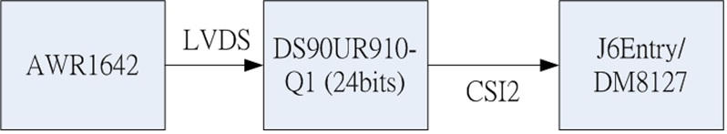
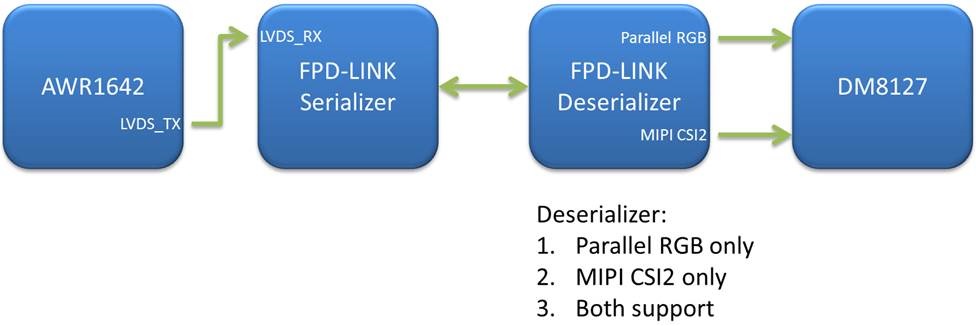
I want to find FPD-LINK solution for AWR1642+DM8127. Here is my block diagram:

Please give me some advice about FPD-LINK solution.

1. Serializer: LVDS interface

2. Deserializer: Parallel RGB or MIPI CSI2 or both support


Thanks in advance.

B.R.

OC

  • Hello OC,
    We have not tried out the a direct serializer option with AWR1642 since its mostly intended to be a single chip sensor with just a CAN kind of interface for final object data transfer.
    You could possibly use an FPGA to convert the LVDS signals to CSI and then DS90UB953 serialzer to send the CSI data with DS90UB954 deserilizer.

    Regards,
    Vivek
  • Hi Vivek,

    Thanks for your input.

    Please help to confirm if I want to use DS90UR910 between AWR1642 and J6Entry or DM8127 that is ok or not.

    B.R.

    OC

  • Hello OC,

    From the DS90UR910 datasheet it does not look like it can directly take the LVDS input from the 1642 device. I would suggest clarifying the details about FPD devices from the High Speed Interface E2E forum

    regards,

    Vivek

  • We are going to check detection performance of AWR1642. So, we need a RAW data recorder, if the detection fails, we will go back to check the algorithms by RAW data, so we need to record LVDS output of AWR1642.

    Here, we like to know the output format first,
    1. RAW data is packed as16 bits? Or 24 bits? (Original ADC data is 10 bits)
    2. What is LVDS? Is it FPD-Link II or III or others?
    3. How to add synchronization signal (frame; chirp information)?
    4. Which LVDS chip can connect AWR1642? Convert to LVCMOS or CSI-II? Either one is OK. (Like DS90UR910Q1?)

    rc.cheng
  • Hello,
    Depending on your application code the "rlAdcBitFormat" API will configure the ADC bits. You can find the details on this API in the SDK document and you will find that this has a parameter "rlUInt32_t rlAdcBitFormat_t::b2AdcBits" which selects the ADC mode to be 12/14/16 bits . There is no 10 bit ADC mode. Once this is selected the same ADC width is followed on the LVDS data (12/14/16 bits).
    The LVDS is not a FPD link format. You can refer to section 5.10.4 of the AWR1642 datasheet to see the LVDS interface and timing protocol followed in this interface.

    To add synchronization or any other user specific headers you can refer to the capture demo application (part of the SDK) to see the sample code to do the same.

    Regards,
    Vivek
  • Dear Vivek:

    Thanks for your immediate response.

    Could you recommend a LVDS chip which can connect to AWR1642, the LVDS output can be CSI-II or LVCMOS?

    Best Regards,
    rc.cheng
  • Hello RC Cheng,
    I am not aware a TI chip that receives this LVDS data format directly, typically we use an FPGA to receive the LVDS data.
    The LVDS signal is neither CSI not LVCMOS , as mentioned above you can refer to section 5.10.4 of the AWR1642 datasheet for the electrical specs also of the LVDS interface.

    regards,
    Vivek
  • Dear Vivek:

    My question is to find aTI convert chip, which can convert LVDS(output of AWR1642) to CSI-II or LVCMOS?

    Or, you can ask LVDS team which chip is capable to do this function.

    Thanks
  • Dear Vivek:

    Could you find a TI LVDS convert chip, which can convert LVDS(output of AWR1642) to CSI-II or LVCMOS?

    Thanks,