This thread has been locked.

If you have a related question, please click the "Ask a related question" button in the top right corner. The newly created question will be automatically linked to this question.

Is Star Topology of MODBUS-RS485 Possible?

Other Parts Discussed in Thread: SN65HVD1792, SN75ALS171A, SN65HVD82

Hi All, 

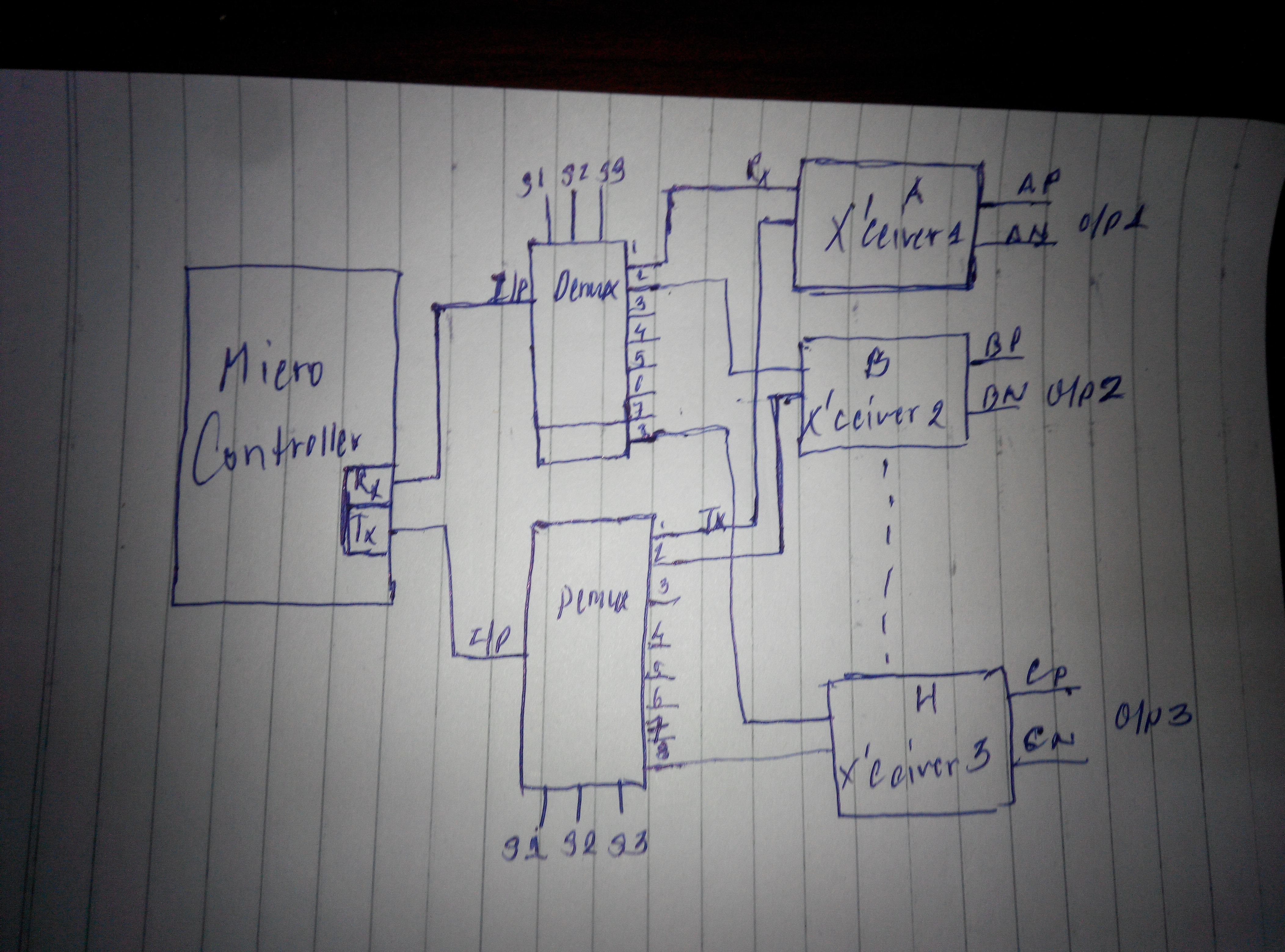
I have an industrial project where there will be one master controller connected to six (6) slave controllers. The physical location of the plant is such that it would be very much feasible for me to connect the slaves with the master in star topology as below. 

The distance would approx. be equal to 600 meters. 

I know that RS485 and Modbus both are serial bus topology but is there any way I can make a star connection come true? What care do I need to take in order to avoid reflections? What maximum speed that can be achieved? Termination resistors? Will master be overloaded if each wing in the star is terminated? Is termination actually required?

Is there any way I can MUX the slaves? 

I am looking for a very robust solution.

Thank you,

Rahul  

  • Hi Rahul,

    thanks for your question.

    In general such a star topology can not be realized with a "simple" RS-485. The reflections that would be caused by these long stubs (connections between your main bus and the slave nodes) make a reliable data transmission impossible. If you would terminate every single node you would end up with 7 times 120 Ohms (120 Ohm twisted pair assumed) in parallel, which results in a 17.14 Ohms load for the differential driver.

    If I calculate the resulting differential output for this scenario (for the SN65HVD1792 as an example), it results in a VOD of approximately 1V which is 0.5V below the minimum differential voltage defined in the RS-485 standard. I used the graphic below which you can find here: SN65HVD1792 data sheet on page 11.

    An option to "hide" the stubs is to place RS-485 repeater at every connection to the main bus, which means a big effort in terms of required parts. You can have a look on our reference design showing how to implement such a repeater here: RS-485 repeater

    The best way to implement RS-485 networks with a focus on robustness an signal integrity is a daisy chain topology which in your case would cause an enormous wiring effort, if the slaves can not be connected without routing back to the master.

    A more interesting concept is a muxing of the slaves you have mentioned. Depending on the number of free i/o pins of your controller you could either use a multi channel transceiver like the SN75ALS171A (3 channels), which would de facto implement separate RS-485 buses for every master-slave network, or you could mux the single ended drive and receive signals for this multi channel transceiver or the differential signals on the RS-485 side with a single channel transceiver (so you would only need 2 controller pins for drive and receive). In this case no communication could be initiated by a slave, the master would decide which slave is connected to the bus.

    To come up with further recommendations I would like to have some input from your side:

    1. What are your requirements for the signal levels on the controller side (5V, 3.3V, or 1.8V)? And how many pins are free to use for the communication?

    2. Do you want to implement your system with 5V or 3.3V RS-485?

    3. Which data rate are you targeting?

    4. Is your total length calculated as 6x 100 meter for every single slave or is every slave 600 meters away from the master?

    If you have any further question, please feel free to ask.

    Thank you and best regards,

    Chris

  • Hi Chris, 

    Thank you for your reply. 

    Few updates in the design. The project is still in preliminary phase. Now there will be 8 slaves with master. The protocol will be such that only Master initiates the communication. Most probably it will be MODBUS. Please suggest if anything better can go well. 

    About SN75ALS171A, it really seems a good solution. Can I configure it in the below manner? i.e. Using a single UART port of micro-controller I combine the Drives and Receives and Enables and have three outputs...? I just have one UART for all 8 slaves. I think you mean to say the same thing. 

    I have thought of one other idea. Don't know if that's reliable. 

    I have also seen few RS485 Splitters. Would that concept be applicable? Is there any product for such design in TI? 

    Answers to your questions. 

    1. What are your requirements for the signal levels on the controller side (5V, 3.3V, or 1.8V)? And how many pins are free to use for the communication?

    Answer: 3.3V or 1.8V (Microcontroller is not yet finalized). We will have sufficient pins for communication. 

    2. Do you want to implement your system with 5V or 3.3V RS-485?

    Answer: 5V will be more robust right? What is the difference between both? 5V is TTL and 3.3V is CMOS...right?

    3. Which data rate are you targeting?

    Answer: Speed is not a critical factor. 9600 baud rate will do. We just have few bytes to transmit at a time. 

    4. Is your total length calculated as 6x 100 meter for every single slave or is every slave 600 meters away from the master?

    Answer: Nope. It is between individual slave and master. It will be between 600 meters to 1000 meters. 

  • Rahul,

    I suggest a separate RS485 transceiver in the master device for each slave port. With good fail safe and master initiation, you may send data to all slaves at same time. The receiver lines can be logically AND together to be the incoming stream. One one channel should receive a low signal at any time. This is only true if the slaves only respond to their name.
  • Your MUX photo is also good but be sure the inactive RS485 chips do not have floating inputs.
  • Hi Ron, 

    I will  go with the same MUX logic. To make sure that the inactive slave is not at floating values I will have pull-up and pull-down resistors on differential pair. Hope this makes sense!

    Regards, 

    Rahul Shah

  • Hi Rahul,

    many of our devices have this failsafe feature you described with the pull-up and pull-down resistors integrated. So you would not need to implement that on your bus.

    Another point you should take care of, are the DE and \RE Pins for each transceiver to enable and disable the individual drivers and receivers. After transmitting the data from the master towards a slave you need to switch off the driver on the masterside and at the same time turn on the receiver. Due to the fact the \RE input is inverted you can tie DE and \RE together for every individual transceiver.

    With muxing of these singnals for all your devices you would need 4 GPIO pins of your microcontroller (8 slaves).

    Also take care of the signal levels for the transceiver inputs (especially if you use a 1.8V microcontoller). The minimum highlevel input voltage is 2V for a typical 5V device (SN65HVD82).

    And the voltage level of the R output may exceed the max values of your microcontroller.

    To your questions:

    About SN75ALS171A, it really seems a good solution. Can I configure it in the below manner?

    In case of compliant voltage levels for your microcontroller and the transceiver it may work (else use levelshifting). I need to check if the R outputs are switched into high impedance mode when disabled, else there would be a "signal collision" for all the output signals. And this device has no integrated failsafe. Check this appnote for further info: RS-485: Passive failsafe for idle bus

    I have also seen few RS485 Splitters. Would that concept be applicable? Is there any product for such design in TI?

    This is a module and could be implemented with TI products according to the above mentioned repeater design.

     5V will be more robust right? What is the difference between both? 5V is TTL and 3.3V is CMOS...right?

    A 5V RS-485 is not necessary more robust than a 3.3V version. The key parameters for a robust RS-485 transmission with focus on the transceiver, are the differential output voltage the driver can provide for the given load, and the input theshold levels (sensitivity) of the receiver. For our parts those are typically identical for 3.3V and 5V parts. With TTL in this case only the single ended logic is described for both cases.

    Best regards,

    Chris