First let me explain my setup.
1) I am using an arduino due to drive the SN65HVD230 transceiver.
2) I am using Collin80 due_Can library with the arduino.
3. I have 120 Ohm terminations on each node
4. I have pinned out all connections from the bus to the transceiver and all is correct
5. i have pinned out connections between transceiver and arduino due - all are correct
6. Transceiver works on CAN HS network at 125K
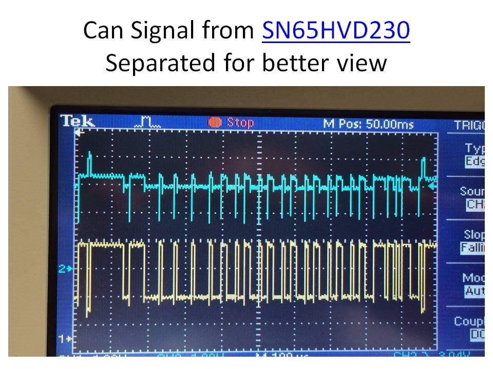
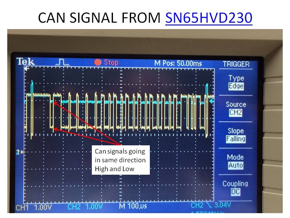
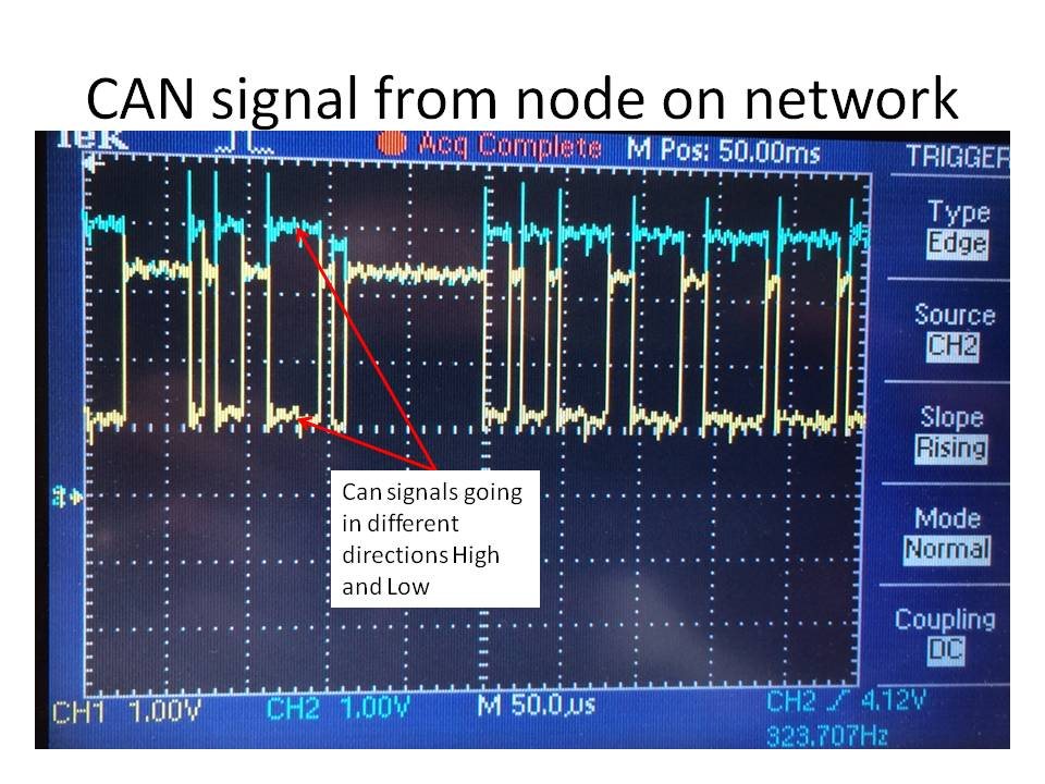
Now I will explain my issue. I am having some issues with my Can bus. The CAN traces I attached below actually turn on the node I need them to (Surprising) on my CAN HS bus but I also have a line going to a CAN HS to CAN LS converter I purchased from EEPOD.com. We use these guys to make testers at my work so I know they are good and know their stuff. I know the CAN messages arent being transmitted on the bus like they should be based upon the Oscope traces below. The CAN_H and CAN_L signals should be going in the opposite directions when transmitting a "1" on the bus I believe. But from my device the square wave is going in the same direction and not opposite directions. In addition the CAN_H signal is a lower voltage change than CAN_L. I think this is why the HS network still works there is enough of a difference in the levels that it still sees 1's and 0's with the differential voltage. But I also think that this is causing the CAN HS to LS converter to not work properly. I am looking for any help on pointing me in the right direction of where to start troubleshooting to correct this issue.


