Because of the Thanksgiving holiday in the U.S., TI E2E™ design support forum responses may be delayed from November 25 through December 2. Thank you for your patience.

This thread has been locked.

If you have a related question, please click the "Ask a related question" button in the top right corner. The newly created question will be automatically linked to this question.

SN65HVD23x 3.3-V CAN Bus Transceiver

Other Parts Discussed in Thread: SN65HVD230

Hello,

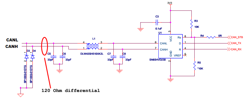
I am having a CAN network system with 4 nodes. All the nodes have SN65HVD230 CAN transceiver. For ESD protection, SP1003-01DTG, TVS diode from littelfuse is used from both CANH and CANL lines to ground.

Issue is that the diode gets shorted to ground.

What can be the cause of this? 

  • Hi Uhtis,

    There may be some damage to the diodes. Have you confirmed that the short goes away when you remove the diodes from the PCB? If so, what kind of stresses could the diodes have encountered during your testing? SP1003-01DTG is rated for high-energy transient pulses (as defined by IEC 61000-4-2/4/5), but other stresses (like a short to a DC power supply) could still be problematic.

    Regards,
    Max
  • Please see the schematics. Is there anything i missed out while choosing TVS?

  • yes, the short goes when diodes are removed. Any other parameters to be aware of?
  • No, it looks like these diodes should be a good fit for this application. They will limit the common-mode range that can be supported slightly; since they will be forward biased below -0.8 V and reverse biased above ~5 V, the voltages on the CAN pins should remain within this range. Other than that, though, I don't see an issue - they should clamp the voltage to within the absolute min/max values of the transceiver and not present too much capacitance to interfere with normal operation.

    Do you have some systems working fine, or do the diodes always tend to break? Is this after some kind of stress testing? Or, is it an issue that shows up after normal operation for some time? Or, is it an issue that is always present immediately when you first test the boards?

    Regards,
    Max
  • All these nodes are connected in daisy chain. Is there any issues ?
  • In general, connecting in a daisy chain fashion is a best practice for CAN networks.

    How is grounding being handled? I notice you used a different ground symbol at the TVS. Are these nodes all referenced to a common ground through their power supplies? Or, is a ground (return) wire distributed along with the CANH and CANL signals? Or, are the reference potentials at each node independent from one another?

    Max
  • It is an issue that shows up after normal operation for some time. In some nodes the diode on CANH gets shorted while in others the diode on CANL gets shorted. During this the resistance measured in the range 10ohm to 2.5kohm. When diode is removed, the short is gone.
  • There is a ground wire distributed along with CAN signals. Also the grounds are separated using a bead, BLM21PG221SN1D.
  • What is the relationship between the grounds used for the TVS and the CAN transceiver/rest of system? Are these tied together somehow (e.g., shorted, capacitively coupled, tied through a bead, etc.)?

    Is there any way to monitor the voltage across the diodes while the system is operating? It would be interesting to see if there are any large voltage excursions happening either on a regular basis (like on dominant/recessive bus transitions) or happening less frequently (and potentially correlated to something else in the system).

    I also just wanted to check on the bus termination scheme. There isn't a terminating resistance shown on the schematic; is this placed elsewhere?

    Max
  • The grounds used for the TVS and the CAN transceiver/rest of system are separated through a bead.

    Regarding the termination, we have 120ohm resistor plugged on the connector, on both the end nodes of the CAN network.

  • Max,

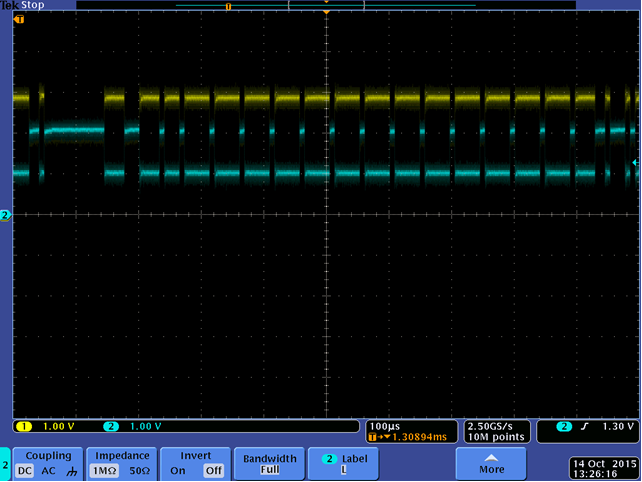
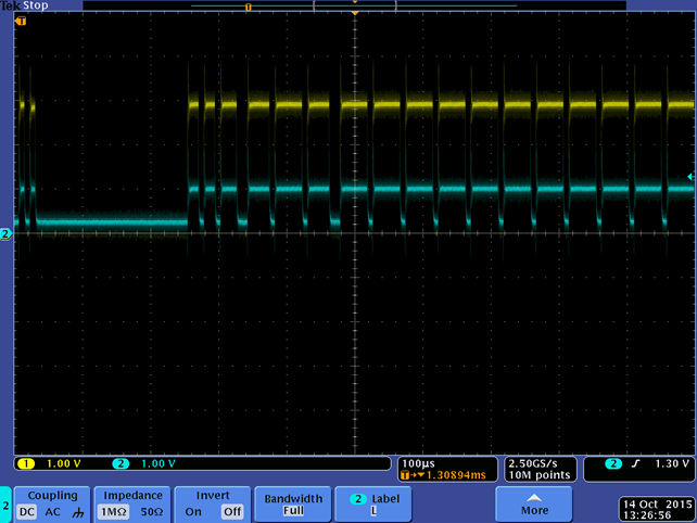
    Please see the waveforms.

    1. CAN H grounded

    2. CAN L  grounded

    uhtis

  • Hi Uhtis,

    Thanks for providing these waveforms. I had a few follow-up questions on them, though.

    What do you mean when you say that CANH and CANL are grounded? Did you short these signals to ground at the connector? (If so, why?) Or, are these the waveforms from failing systems where diodes are damaged and acting as shorts to ground?

    The reason I ask is that in the first waveform there doesn't seem to be a short at all; these are normal CAN waveforms. In the second waveform (CANL grounded), the recessive level is at 0 V but the CANL dominant level is still about 1 V; this would not be the case if CANL were shorted to ground.

    Best regards,
    Max
  • Hi Max,

    Yes, these are the waveform from failing systems where diodes are damaged(in some boards it is bulged) and acting as shorts to ground. At this point of time when the resistance is measured across the CAN lines and ground using multimeter, we got 10ohm to 2.5kohm. In working boards we have the resistance in the range of 64K/57K etc., 

    Hence it is assumed that the TVS diode gets shorted to ground. Also, while hot plugging (plugging the CAN cable in the board) we got upto 8V in these lines. The waveforms are as below. 

  • The 8-V signal during hot plugging is most likely what is causing this damage. At this voltage, the TVS will sink about 2 A (per the TLP I/V curves in its datasheet). This means that the power that it will need to dissipate is quite high (~16 W). This would be OK for a short pulse/transient, but the diode would not be able to withstand this indefinitely.

    Max
  • Max,
    Need to find out where is this coming from? The chip in only 3.3V.
    Regards,
    uhtis
  • Uhtis,

    Yes, you could probe around several points in the circuit with your oscilloscope probe (or a multimeter if the voltage is DC) to find out the source of the 8 V.  For example, before you plug the cable into the board you could take a look at:

    • The voltage at the board's CANH/CANL lines at the connector with respect to the PCB's ground.
    • The voltage at the CANH/CANL signals on the cable's connector with respect to the cable's ground.
    • The voltages at the cable terminals (CANH/CANL/Ground) with respect to the PCB's ground.

    If the higher voltage is already present before the cable is plugged in, then it points to grounding/power supply differences that you would need to debug.  If the voltage shows up after the cable is inserted, then the problem would be elsewhere.

    Regards,
    Max