Other Parts Discussed in Thread: SN65HVD233, ADS1262
Hi,
We have a board with SN65HVD233 3.3V CAN transceivers. We monitor our CAN interfaces with PCAN-USB (CAN-to-USB) converter of Peak Systems.
Link : http://www.peak-system.com/PCAN-USB.199.0.html?L=1
Let me define our problem. We had a Revision 1 board where we have no CAN bus problem. SN65HVD233 and PCAN-USB communicated without any problem at 250 Kbps.
Having made several capacitor-resistor additions on completely irrelevant section of the PCB, I have Revision 2 board manufactured. And now, i have the following problem :
1) SN65HVD233 cannot communicate with PCAN-USB at 250 Kbps. Receive-RX (From PCAN-USB to SN65HVD233 ) works perfectly. Transmit-TX (From SN65HVD233 to PCAN-SUB ) doesn't work at 250 Kbps. Weirdly, while i cannot transmit data 00 to PCAN-USB, PCAN-USB somehow manages to capture some of the data AA
2) When, we reduced CAN bus speed to 10 Kbps, we managed to establish a somehow stable connection. Using this 10 Kbps, we tested other functions on the board. But this connection also crumbled all the time.
3) Other functions on my Revision 2 board, ADC, DAC, Digital IOs and EEPROM all work as intented. So, there is not a general problem on PCB.
4) I connected CAN interfaces of Revision 1 and Revision 2 boards to each other. In this scheme, my Revision 2 board send a data at 250 Kbps, Revision 1 board reads it and transmit it back after incrementing data by one. This way i made sure that SN65HVD233 Chip or my CPU on Revision 2 board is working fine.
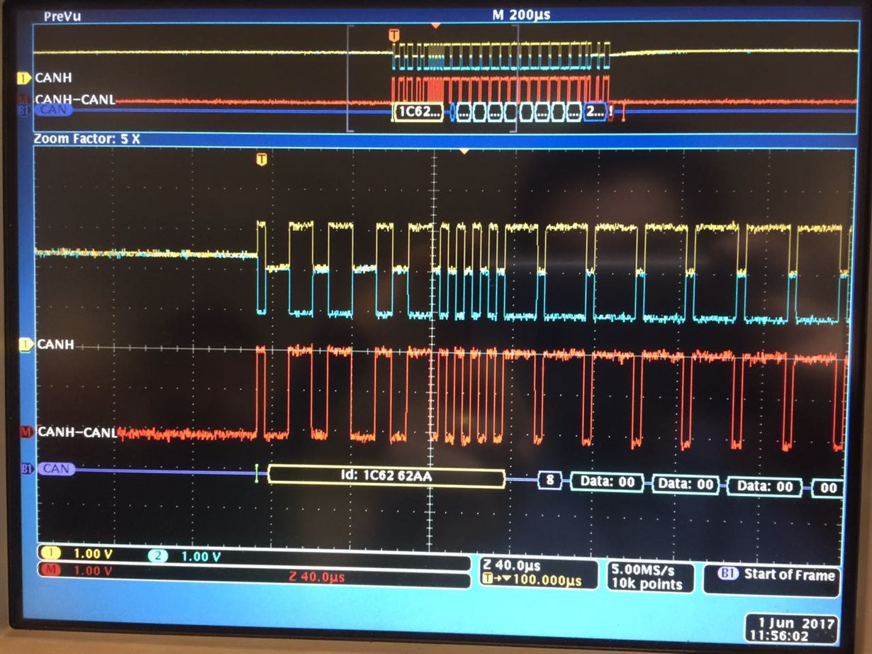
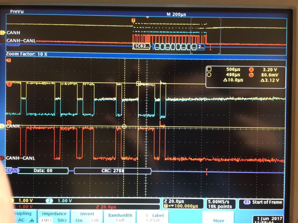
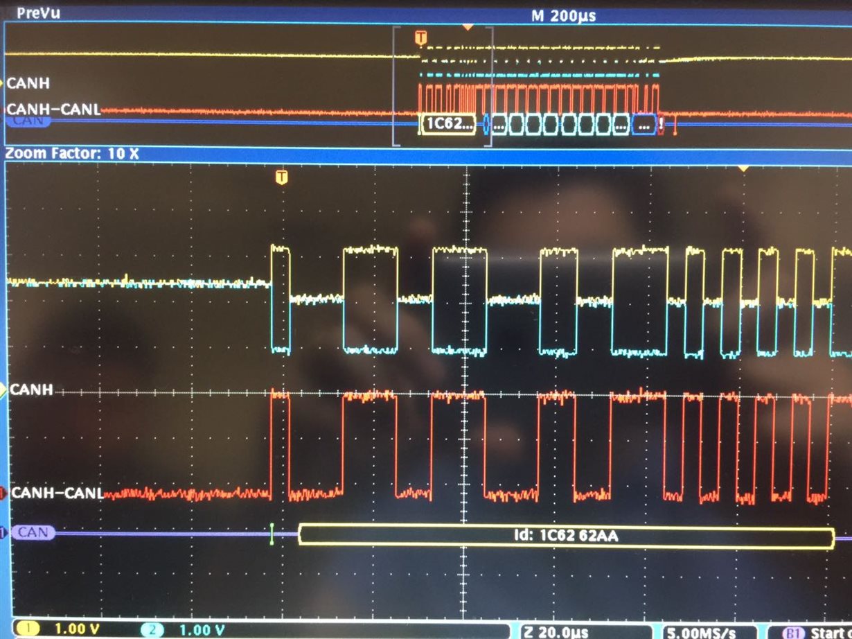
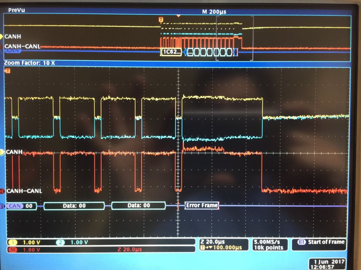
5) During the last few days, i monitored CAN outputs of Revision 2 board on Oscilloscope. What is see is that; Identifier, data and CRC are all correct. However, when i connect PCAN-USB to the board, PCAN-USB interrupts data at one point (changing everytime) and places an error frame. That's why i can't read data from PCAN-USB.
6) Timings and signal quality is indistiguishable from Revision 1 board. However, i didn't care much attention to voltage levels as they seemed similar. I will now look into this aspect now. Before that, i wanted to consult to you :
- As i tried almost anything during the last few days, i now think problem could have something to do with 3.3V and 5V interoperability. Yes, my Revision 1 board works fine with PCAN-USB but i suspect that Revision 2 PCB manufacturing may broke down already fragile (and so far unknown) balance. One other reason that pushes me to think like this is that there is 3.3V-GND impedance difference between Revision 1 and Revision 2 boards.
- SN65HVD233 datasheet and SLLA337 (Overview of 3.3V CAN XCVRs) document states that 3.3V TI CAN transceivers are compatible with 5V CAN transceivers. But, the points i put above makes me suspect a 5V interoperability problem. ( Especially working connection between Revision 1 and Revision 2 boards). By the way, i used 3 different PCAN-USB cables, so i am sure that PCAN-USB cable is not the problem.
What are your opinions ? Do you think it may be due to different voltage systems ? Or do you have any other ideas that i am missing ?
Thanks in advance, any help is appreciated.
Regards,
Mehmet
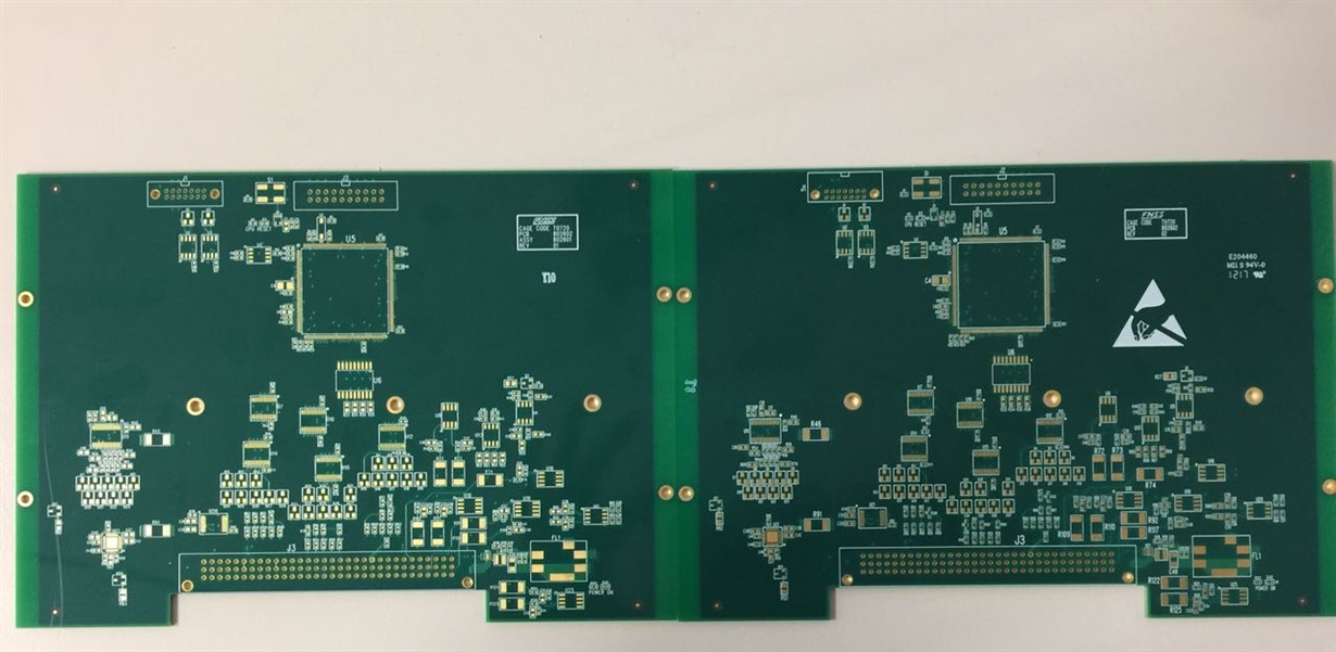
Note : In order to show you there is no layout differences between Revision 1 and Revision 2 boards, i am adding their photos. SN65HVD233 ICs are on the upper left.


