This thread has been locked.

If you have a related question, please click the "Ask a related question" button in the top right corner. The newly created question will be automatically linked to this question.

ISO1050: Interference on the CAN bus

Part Number: ISO1050

Hi team,

There are only two nodes on the CAN bus. The termination resistance on both ends of the CAN bus is 120Ω. One node on the CAN bus is the [1] board and the other node is the [2] board. Baud rate 500K. The CAN circuit is as follows:

The following waveform is the waveform between the CANH and CANL of the [1] board.

CAN bus length 35 meters,

CAN bus length 8 meters

The problem cannot be solved by shorting L9, L10.

The waveform between the CANH and CANL of the [2]board is very good and has no problem. 

Thanks,

Amy

  • Hi Amy,

    Thank you for posting to E2E! Although the waveform for the 35m CAN bus length looks noisier than the one for 8m length, are there any moments where the data on TX and RX lines of the ISO1050 do not correlate to the HIGH/LOW signals on the CAN bus?

    35m distances should not be problematic for CAN data transmission in most applications, so it will be helpful to confirm that inputs to the ISO1050 are matching the outputs by checking TX, RX, and CANH, CANL waveforms on the same oscilloscope screen. Please let us know the result.

    Respectfully,
    Manuel Chavez

  • Hi Amy,

    Did Manny response address your issue?

    If not, could you please clarify your issue by giving more details?

    Regards,

    Alfred

  • Hi Manuel & Alfred,

    Thanks for your response. 

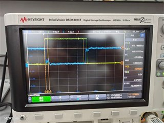
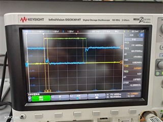
    The customer has provided the following oscilloscope waveforms

    Channel 1 is TX to GND1 (ground on DSP side), Channel 2 is RX to GND1 (ground on DSP side), Channel 3 is CANH to CANL

    What could be the possible reason

    Regards,

    Amy

  • Hi Amy,


    Thank you for following up with the customer!


    The image is blurry and I have to guess that Channel 1 and Channel 2 are the yellow and green waveforms. Channel 3 is the blue waveform, right? Based on the title of this post, the concern is the interference on the CAN bus right?
    If so, it is not uncommon to see reflections on CANH and CANL bus due to the impedance mismatch along the path from one device to another device.


    1. Has the customer faced any functional issues?
    2. Has the interference caused any performance degradation?
    3. I assume that the data rate is 500kbps as I can't see the division from the image. If so, was the provided waveform taken with an 8-meter cable?
    4. Could you please provide the single-ended CANH and CANL waveforms?


    Regards,
    Alfred

  • Hi Amy,

    Do you have any update?

    Regards,

    Alfred

  • Hi Alfred,

    Thank you for your follow-up.

    You are right. Channel 1 is the yellow waveform. Channel 2 is the green waveform. Channel 3 is the blue waveform.

    Yes, the concern is the interference on the CAN bus.

    For your 4 questions, the customer only returned the third, that is, the waveform was measured at a data rate of 500kbps and a bus length of 8 meters. If the customer has other updates, I'll let you know.

    Regards,

    Amy

  • Hi Amy:

    Thanks for providing the additional information to clarify the customer concern.

    As Alfred stated, this is normal CAN behavior. CAN receiver thresholds are around 750mV (see below) and these reflections will not affect the performance.

    Hope this answers your question. Please feel free to click on the "Ask a related question"  button on top right if you have further questions.

    Regards,

    Dushmantha