A related question is a question created from another question. When the related question is created, it will be automatically linked to the original question.
If you have a related question, please click the "Ask a related question" button in the top right corner. The newly created question will be automatically linked to this question.
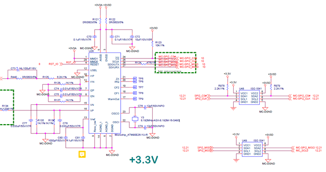
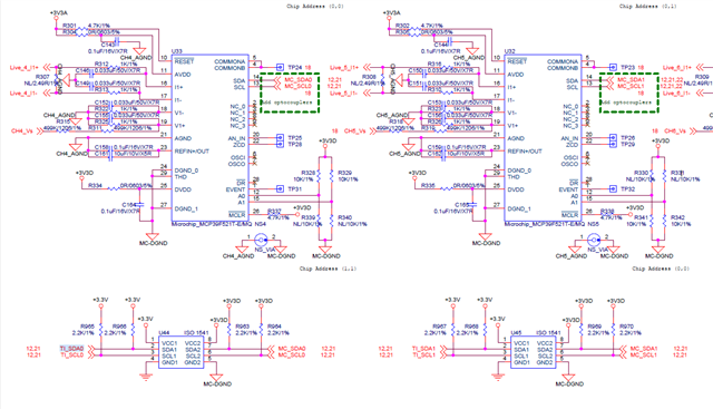
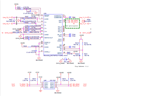
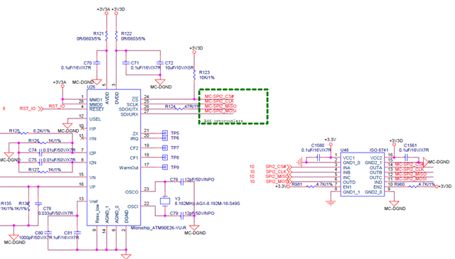
Regarding U44, U45, and U46, the connections all look good. For U48 and U49, it looks like the signals being isolated are SPI, and not open-drain signals like I2C, so a standard digital isolator like ISO6741 can be used instead.
For the cases where ISO1541 is used, TI's new ISO1641 is a more robust I2C-capable isolator that is pin-to-pin compatible with ISO1541, and we recommend replacing all instances of ISO1541 with ISO1641.
Please let us know if you have additional questions.
If ISO1541 is used to isolate UART and SPI signals, pull-up resistors are needed on the signal lines on both sides of the isolator to provide the HIGH signal output states.
Digital isolators like ISO77xx and ISO67xx devices are recommended instead of an I2C isolator for SPI and UART signals. If package size is a concern, ISO6720 and ISO6721 devices in similar "D" packages are available.
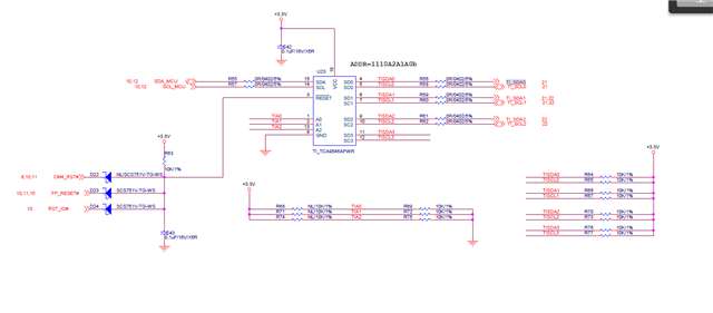
Thank you for your response! It seems like the ISO6741 is configured correctly, and the only necessary change might be to switch the connections of MISO and MOSI lines on the digital isolator.
Since MISO is an output to the M90E26, it should drive an input channel of the isolator like IND while MOSI is an input, so it should be connected to an output pin like OUTC to receive data from the MCU. In short, the connection pairs to pins 5 and 12 can be switched with the connections to pins 6 and 11 respectively.
Please let us know if you have additional questions or concerns.