This thread has been locked.

If you have a related question, please click the "Ask a related question" button in the top right corner. The newly created question will be automatically linked to this question.

ISO1412: ISO1412 – Module Parallel Question

Part Number: ISO1412

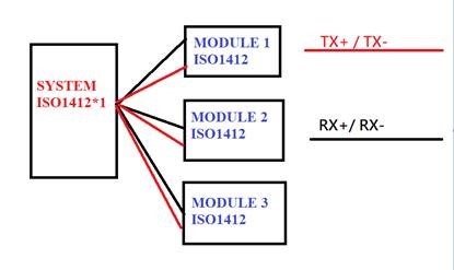
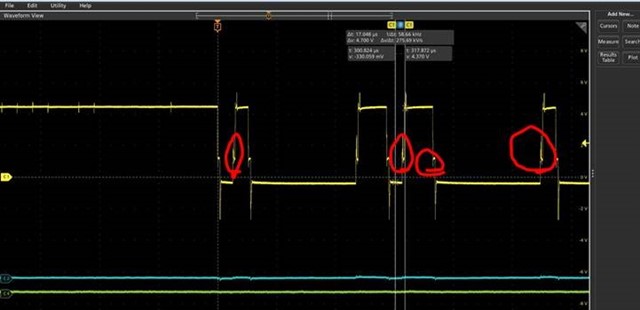
The test we used is shown in the figure below. In the test, only SYSTEM to MODULE 1 is connected, and the measurement graph is normal, but when the SYSTEM is connected to MODULE 1 + MODULE 2, and the RX+ /RX- looks very strange (red mark). May I know is this correct? And what caused this problem.

BR, Gary

  • Hi Gary,

    Thanks for reaching out.

    I am assuming TX+/TX- here are Y/Z of ISO1412 and RX+/RX- are A/B of ISO1412, please confirm.
    I am also assuming the waveform that you have shared is A/B differential waveform (difference between A and B).

    Please do share the schematic showing connections all four ISO1412 devices and their connections to help us review if the connection is okay. I couldn't read voltage and time scales in the waveform, please do also share us with a better resolutions waveform which also shows the voltage and time scales to review and comment if anything wrong in the waveform. Thanks.


    Regards,
    Koteshwar Rao

  • Hi Rao,

    Thanks for your help.

    The host circuit show in below. The slave will remove 56 ohm between bus.

    There are two pictures in my test. The first picture is the RX+/RX- differential mode signal which is normal level after I connected slave module 1. The computer can distinguish the message. The second picture shows when we connect slave module 1 and slave module 2. We find the low level voltage change from 0V to 3V.

    Question:

    1. the low level voltage is correct or not? why have this change?

    2. Do you have reference design for 1 host + 3 slave application? Could you share design schematic?

    3. Please help to make sure the waveform is correct or not in previous post.

    connected to slave module 1:

    connected to slave module 1 + slave module 2:

  • Hi Gary,

    Thanks for sharing schematic, waveform and other additional information.

    I have reviewed the schematic and I see that the 56Ω termination resistor is used on both A/B and Y/Z lines of the master. Since the device ISO1412 is used in full-duplex mode and since each transmission line is unidirectional, the termination resistor is only needed at the receiving end. i.e., A/B of master and A/B of farthest slave should have the termination resistors and Y/Z pins should not use any termination on their pins. Please request customer to make this change and test again. ISO1412 might be currently overloaded due to dual 56Ω termination resistors at both end.

    1. the low level voltage is correct or not? why have this change?

    The waveform images shared earlier and now are still very low in resolution, I cannot ready any voltage or time scales clearly. Please do share higher resolution images. If you are unable to upload them here, then you can also send me an email with higher resolution images.

    2. Do you have reference design for 1 host + 3 slave application? Could you share design schematic?

    I do not believe we have such a reference design, I will check on this and come back again.

    3. Please help to make sure the waveform is correct or not in previous post.

    Please share higher resolution waveform to be able to review them and comment. Thanks.


    Regards,
    Koteshwar Rao