This thread has been locked.
If you have a related question, please click the "Ask a related question" button in the top right corner. The newly created question will be automatically linked to this question.
hi,
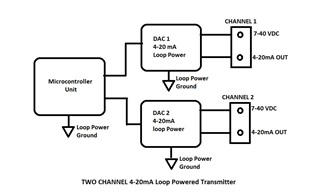
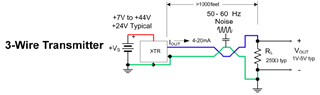
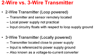
We trying to design two channel 4-20 mA loop powered transmitter for Temperature and Relative humidity. my issue is, how to use ground signal in loop powered design. i have attached block diagram image for my application.if you have solution for loop powered 4-20 mA. please support.
Hi Fularam,
You have two 4-20mA V-to-I design options.
XTR116/XTR117 parts are 2-wire 4-20mA transmitters, see the 4-20mA current loop in blue and red twisted pair wires below.
You will need two of DAC8551s and implement the following loop powered 2-wire transmitters, see the link below and DAC8551 datasheet. DAC8551 is powered by XTR116/XR117 transmitter, where loop powered grounds are floating. The transmitter is powered by red ower line from Vloop supply, shown in the image above, and 4-20mA current loop is returned in red line and convert the loop current back to voltage via 250Ω load.
The above application note and EVB are not sold in store, but you may follow the recommendation and implement a similar design scheme + PCB recommended layout. I believed that your block diagram above is represented in the 2-wire 4-20mA transmitter configuration. MCU is communicating to DAC8551 digitally vial serial interface.
XTR111 is 3-wire 4-20mA transmitter. where XTR111 is locally powered and 4-20mA current loop is shared via the ground line, see the image below.
Below are the main differences between 2-wire and 3-wire transmitters, see the attached file below.
Enclosed is a copy the above slides about 4-20mA transmitters.
If you have additional questions, please let us know.
Best,
Raymond
Hi Fularam,
I am going to close this inquiry. If you have additional questions, you may still reopen this thread.
Best,
Raymond