This thread has been locked.

If you have a related question, please click the "Ask a related question" button in the top right corner. The newly created question will be automatically linked to this question.

ISO1212: ISO1212

Part Number: ISO1212
Other Parts Discussed in Thread: ISO1211

Dear members, 

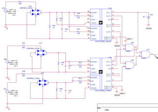
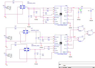
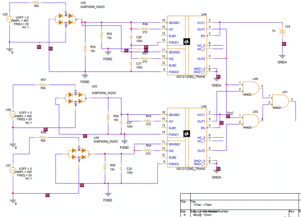
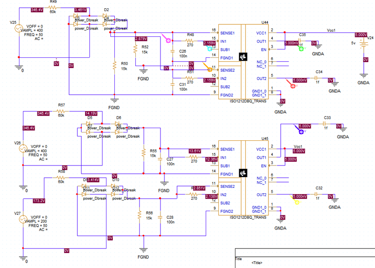
As I'm working on VAC detection circuit, I found this chip. it can help me perfectly make the circuit. I wanted to know if there is possibility to design the exact value, I mean for example I have input VAC of 400v and below 200VAC  it should give me 0 (digital).

for detecting presence of all three lines (as my system is three-phasic) I know that I need to implement 2 of this chip. and then maybe by connecting the outputs to an and gate,k checking the existance of each line. On the other side I want it gives me a zero when the voltage is behind 200vac in each line. I tried to make the circuit using optocopulers but still I'm not able to make it. any idea?

  • Hi Farzaneh,

    Thanks for reaching out for showing interest in ISO1212.

    The input of ISO1212 has Schmitt type thresholds which offers good immunity against noise by having a hysteresis. Schmitt type inputs will have VIH and VIL thresholds where any input voltage >VIH will give a HIGH output and any voltage <VIL will give you LOW output. When the input voltage is in-between these two levels, the output holds the previous value as is.

    If your requirement is to have a LOW for voltages <200V, this can achieved by designing worst-case VIL to be at or slightly above 200V.

    Please refer to the below application note and a threshold calculator spreadsheet which will should help you design your system.

    How to Design Isolated Comparators for ±48V, 110V and 240V DC and AC Detection (Rev. A)

    ISO121x Threshold Calculator for 9V to 300V DC and AC Voltage Detection

    Let me know if you have any further questions, thanks.


    Regards,
    Koteshwar Rao

  • Hello,

    I tried to do the SCH regarding the documents you mentioned. my simulation doesn't work because I have some floating pins that according to the datasheet they can be left floating. on the other hand I'm not sure about the design. Can you take a look and tell me if it seems OK or not?

    Thanks in advance.

    Farzaneh

  • also I tried by conneting EN to vcc...

  • Hi Farzaneh,

    Thanks for sharing the schematic.

    I took a look at the schematic, please see my comments below. Thanks.

    1. The FGND1 of U44 doesn't seem like has a return path, this part of device might not function. Maybe you meant to short it to FGND2 of U44.
    2. The schematic of U45 looks good.
    3. I believe you meant to have 15kΩ for R50, R52, R55 and R56 instead it is currently specified as 15Ω. I guess this just a typo.
    4. V24 is mentioned to be 6V. The device supports a max voltage of 5.5V, please reduce this value to 5.5V or lower.
    5. I see that you have used RSENSE (R48, R51, R53 & R54) value of 128Ω. The device has been characterised for values from 200Ω to 562Ω. Hence, please use a value between these. Using a lower value can lead to thermal issues.


    Regards,
    Koteshwar Rao

  • Hello, 

    Thanks a lot for your response. I changed my circuit to this one, according to your comments and also the EVA doc below: "">www.ti.com/.../sllu254a.pdf

    In all the outputs I just see 0 voltage. 

    I can't find the problem!

    Regards

    Farzaneh

  • My circuit should be an analog one. there is no connection to Micro. I don't know what to do with EN pin. right now it's connected to VCC1.

  • Hi Farzaneh,

    Thanks for updating the schematic. I still see some concern in the the power supply to VCC1. The resistor divider will not be able to bring down the voltage and supply the isolator reliably, it is prone to loading. For example, any current flowing through R59 will increase the voltage drop across itself and then drop the voltage at VCC1. This could lead to device being turned OFF.

    Could you please change V24 voltage to 5V and retest again?

    Please do also share us the simulation file that you are using and let us know what simulation tool you are using. We can try to replicate your problem and debug. Thanks.


    Regards,
    Koteshwar Rao

  • Hey,

    I changed it to 5v, still nothing. Simulation and SCH have been attached. I use ORCAD.

    sim.rar

    Thanks 

    Farzaneh

  • Hi Farzaneh,

    Thanks for sharing your schematic!

    I replaced the full-bridge rectifier with 4 diodes because the sub-circuit is not included in the file you shared.

    I also removed the AND2 logic as its version conflicts with my local library version.

    I ran the simulation and found that all the outputs are zero as you mentioned.

    Then, I found that the Vcc1 net alias wasn't defined or accidentally removed from U44.

    I added the net alias on the U44 VCC1 net so that U45 now has a 5V supply.

    With this fixed, The out1 of U45 goes high to 5V as shown in the purple curve.

    If I lower the VAMPL of V26 to 200V, the output goes to 0V.

    Regards,

    Alfred

  • Hello Alferd,

    yeah I could see that it was working. thanks a lot. But I have a question. As you might have read my purpose of using this chip at the beginning, I need to detect the three phase on my board. I was thinking of using this chip and then adding the outputs to an AND gate. Let's say I need to have all the lines "1", but in U44 both of the outputs are 0, although both supplies are 400VAC but I get 0 in both outputs. How can I fix it? 

    Regards

    Farzaneh

  • Hey,

    I used ISO1211, and it works perfectly. I just want you to confirm if everything is fine with this design. I have doub if I can use ISO1211 for AC detecting. 

    Thanks a lot,

    Farzaneh

  • Hi Farzaneh,

    For U44, in1, in2 and sense1 and sense 2 are connected to the same source. Hence, they are drawing 2X current from the source.

    In order for U44 to be able to detect the current at 400VAC, you will need to reduce the R49 from 60k to 30k.

    Regards,

    Alfred

  • Hey, 

    yeah later I understood what was going on there. and due to that I changed U44 to ISo1211. and it seems that it's working properly. My question was if I could use this chip for AC detection. 

    anyway. after dedicating too much time I saw that either ISO1212 nor 1211 is available. Do you know any other similar chip to suggest me?

    Regards

    Farzaneh 

  • Hi Farzaneh,

    ISO1212 and ISO1211 are threshold detectors that will work with DC and AC input.

    Unfortunately, we do not have an alternative for these devices. 

    You can use the "Notify me when available" feature on the product pages to get a notification when these products are available.

    Regards,

    Alfred