Because of the holidays, TI E2E™ design support forum responses will be delayed from Dec. 25 through Jan. 2. Thank you for your patience.

This thread has been locked.

If you have a related question, please click the "Ask a related question" button in the top right corner. The newly created question will be automatically linked to this question.

ISO7710: Output Pulsed Instead of Squarewave

Part Number: ISO7710

Hi,

I'm new to digital isolators but have some experience with opto-isolators. To test its functionality, I hooked up ISO7710FD as in the schematic below:
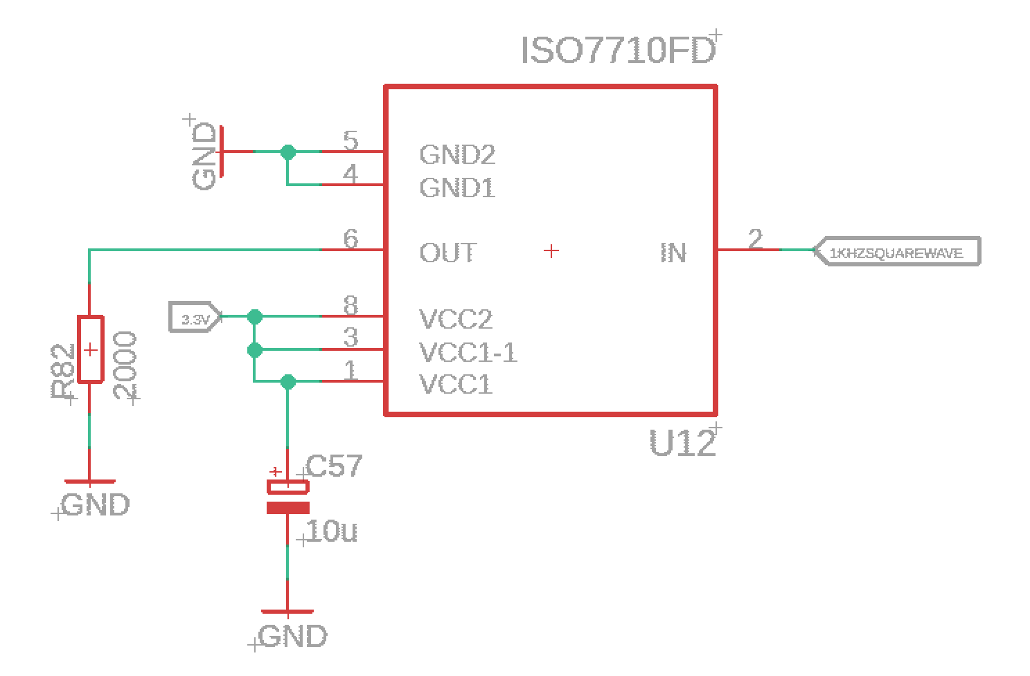
The supplies aren't isolated for testing at the moment. This was my 1KHz 3.3V input squarewave:

I expected the output to be a 1KHz 3.3V squarewave similar to the input, but instead I got a 10KHz 3.3V pulsed output:

Looking at the datasheet, it seems similar to the carrier signal through the isolation barrier- however from what I understand this should be converted to a squarewave before reaching RXOUT. I've tried different passive components on the output (all with the same 1KHz 3.3V squarewave input):

- 2K Ohm resistor alone resulted in output as shown above

- Adding a 150pF capacitor between output and ground had no effect

- Adding a 0.1uF capacitor between output and ground resulted in a 0.8V ~ 1.8V pulsed output

- No passive components resulted in a constant 3.3V high output signal

Another important factor:

- The device's pins were each reached ~388 Degrees Celsius for 5-10 seconds while soldering to a SOIC-to-DIP adaptor

My diagnosis is that the isolation barrier was damaged during soldering causing the carrier signal to appear at the output, however I'm not entirely sure.

What do you guys think? Has anyone seen such an output while working with digital isolators?

Regards,

MZivcec

  • Hi MZivec,

    Thanks for reaching out and for sharing details related to the issue.

    Looking at the datasheet, it seems similar to the carrier signal through the isolation barrier- however from what I understand this should be converted to a squarewave before reaching RXOUT.

    The internal carrier frequency is of much higher frequency, much higher than the max datarate it supports. Hence, the pulsed output you are seeing is not due to internal carrier.

    The device's pins were each reached ~388 Degrees Celsius for 5-10 seconds while soldering to a SOIC-to-DIP adaptor

    The peak temperature for soldering shouldn't exceed the maximum reflow temperature (260C), violating which could result into device damage. This could be the reason for device malfunction. Please see below application mote for soldering guidelines and reflow profile.

    https://www.ti.com/lit/spraby1

    Please do test a new device where you do not exceed 260C and let us know if you see any issues, thanks.


    Regards,
    Koteshwar Rao